The receiver connects to the keypad bus via d and d terminals permitting the alarm panel to be armed and disarmed from remote transmitters. The green led flashes when in standby mode.
Knowing And Doing Computing Archives
Ids x64 wiring diagram. If it is off then there is a problem. 861 004 must be used when any device requiring a current greater than 50ma is connected to a programmable output. 14 installation choose a location for the remote receiver. Ids x64 manuals manuals and user guides for ids x64. We have 6 ids x64 manuals available for free pdf download. The following are what you would need to press on the ids alarm panel keypad.
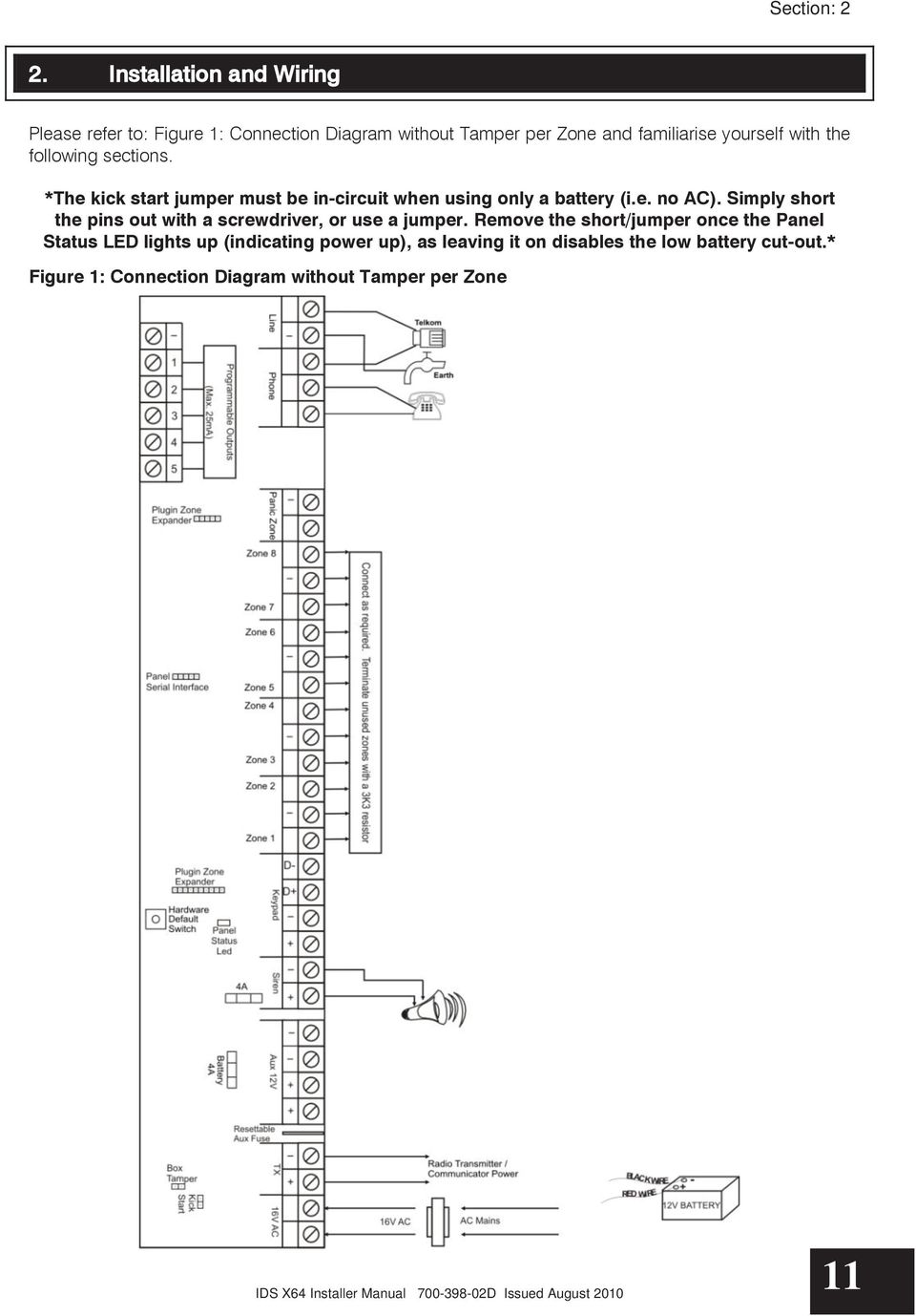
The amber led will be a steady on when it is connected to the bus. Most features are configurable and may be programmed directly through. It has up to 8 partitions and can be expanded from 8 64 zones. Exit and save programming instructions for ids816 panel. Connection diagram without tamper per zone ids x64 installer manual 700 398 02d issued august 2010. Introduction to the ids x64 thank you for purchasing an ids alarm panel.
Ids x64 remote receiver 700 408 02a issued august 2010 5 13 wiring and configuration note. Overview introduction the ids x64 remote receiver is a 43392 mhz rf receiver that is designed to connect to an ids x64 alarm panel. The ids x64 is a versatile bylaw 25 compliant expandable alarm panel. Installer manual training manual user manual quick programming manual. Ids x64 installer manual 700 398 02d issued august 2010 10 1. Installation requirements 214 programmable outputs an ids relay board pn.
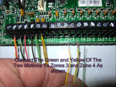
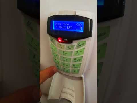
Here we are using zone 8 if you want to use another zone the zone number should be used 8 step 3.
Gallery of Ids X64 Wiring Diagram