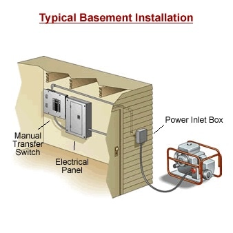
The generator supply power to the homes electric. Breaker contactor or motorised switch socomec diagram.

Auto Transfer Switch Ats Working And Ats Control Panel Wiring Diagram
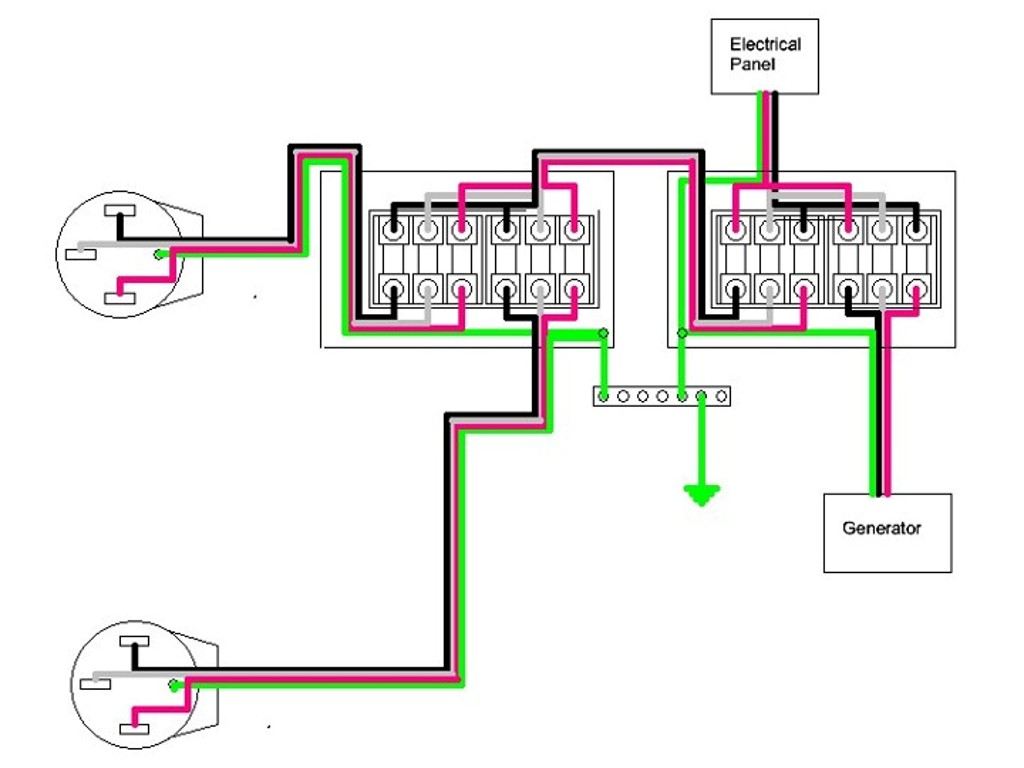
Ats panel for generator wiring diagram. Ats when an electric utility outage occurs the ats will tell the backup generator to start. Variety of ats wiring diagram for standby generator. Generator automatic transfer switch wiring diagram generac with. It is also shows the working and operation for different changeover switches wiring connections like single phase manual changeover switch with generator three phase manual transfer switch connection with generator as well as single phase and three phase automatic transfer switches connections to the 1 and 3 phase generators and main fuse board. A wiring diagram is a simplified conventional photographic depiction of an electric circuit. Wiring the atsgts to the ups the atsgts should be wired to the ups as shown in figure 1 below.
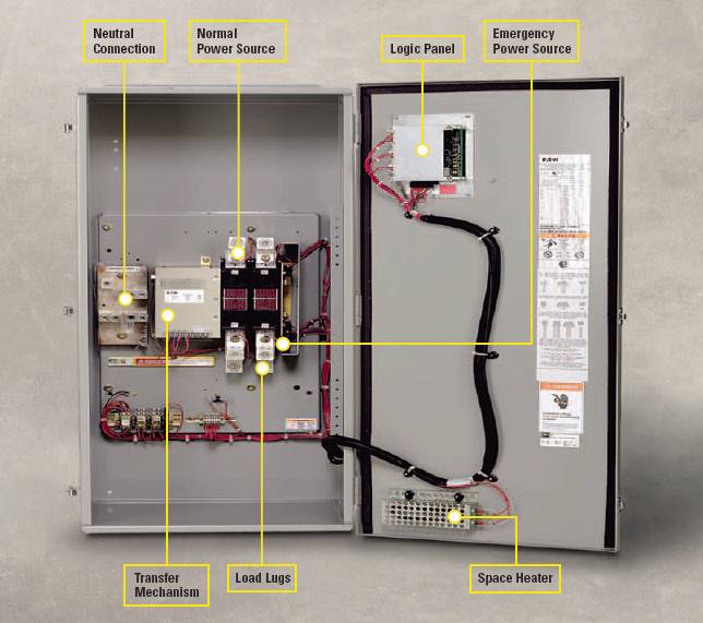
Generac 100 amp automatic transfer switch wiring diagram. Whole house transfer switch wiring diagram awesome 11 plus generator. In the case of an automatic transfer switch ats the switch has the intelligence to sense when the utility is no longer delivering power and automatically starting the generator and then transferring the circuits to the generator. The above illustrated diesel generator control panel wiring diagram is the typical connection wiring diagram of the bek3 automatic mains failure controller. A distribution board also known as panelboard breaker panel or electric panel is a component of an electricity supply system that divides an electrical power feed into subsidiary circuits while providing a protective fuse or circuit breaker for each circuit in a common enclosure. Ats transformer cl ncl g q1 q2 ats genset cl ncl g q1 q2 ats critical load cl ncl g q1 q2 ats non critical load cl ncl g q1 q2 ats standard diagram.
Connecting the current transformers after the mains and generator changeover will allow you to read and monitor the current when the load is connected to the power utility. Once the ats sees that the generator is ready to provide electric power the ats breaks the homes connection to the electric utility and connects the generator to the homes main electrical panel. A wiring diagram is a simplified conventional photographic representation of an electric circuit. Ats wiring diagram for standby generator. To the generator sub panel. It shows the elements of the circuit as streamlined shapes as well as the power and also signal links between the gadgets.
Figure 4 wiring diagram of a manual transfer switch in the off position. Automatic transfer switch amp single phase vac service rated circuit load center 28 pages switch generac power systems rtswg3. Motorised switch cl ncl g q1 q2 ats automatic transfer switch protection arent shown on the following schemes summary. Refer to the smm ownersinstallation manual forvariety of generac amp automatic transfer switch wiring diagram. Ats panel wiring diagram an automatic transfer switch wiring diagram an automatic transfer switch wiring diagram an generators 120 vac 50 amp automatic transfer switch from progressive dynamics generator transfer switch. Generac 200 amp automatic transfer switch wiring diagram sample generac 100 amp automatic transfer switch wiring diagram elegant 16.
Gallery of Ats Panel For Generator Wiring Diagram