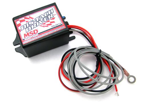
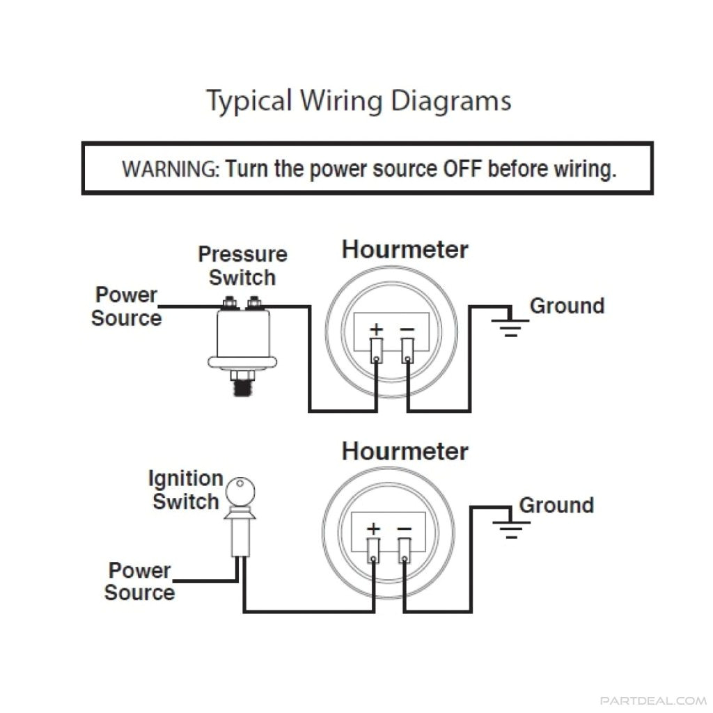
Pin 3 black. Whit wire to one of the sensor wires.

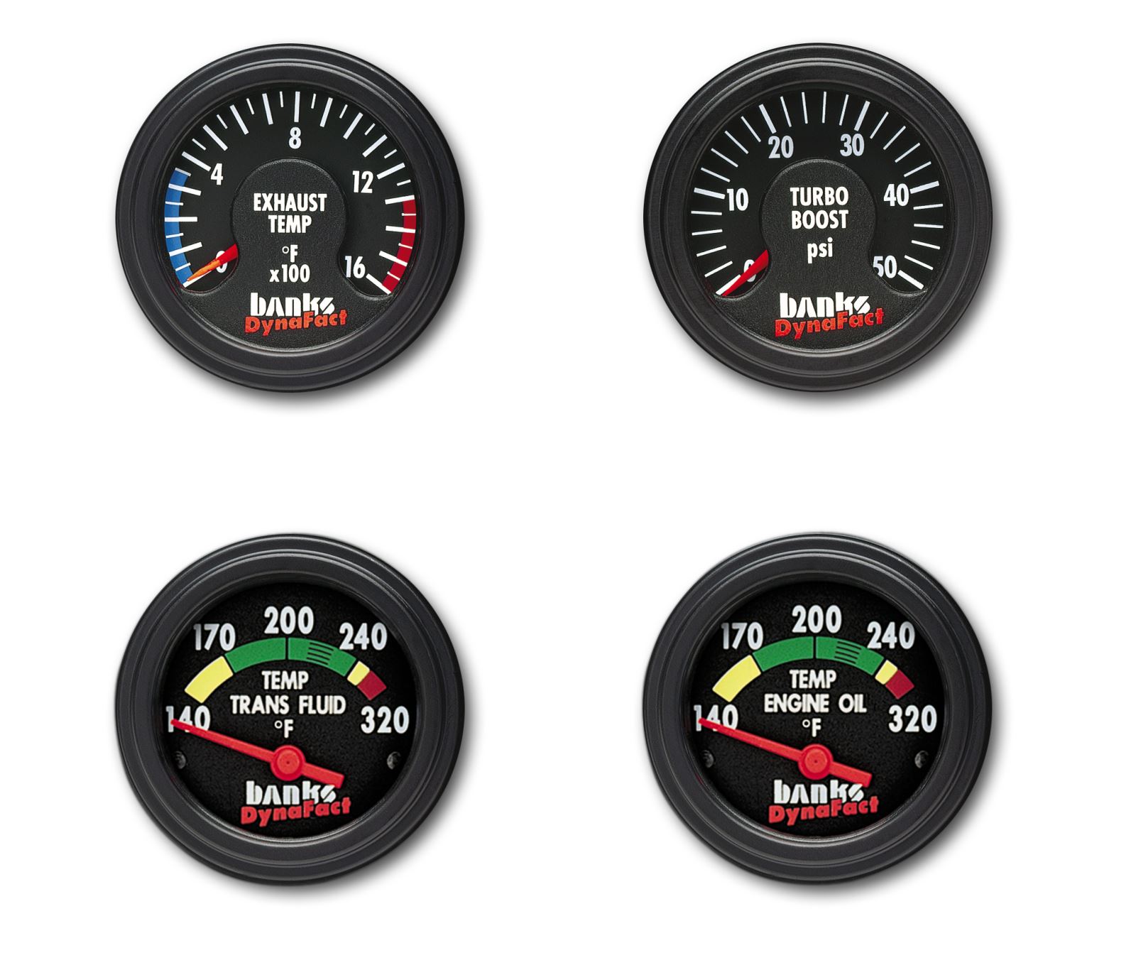
Electric Fuel Pressure Gauge 0 30 Stewart Warner Autometer
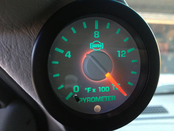
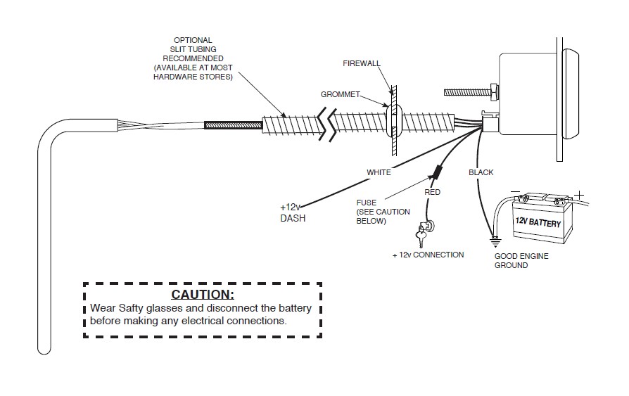
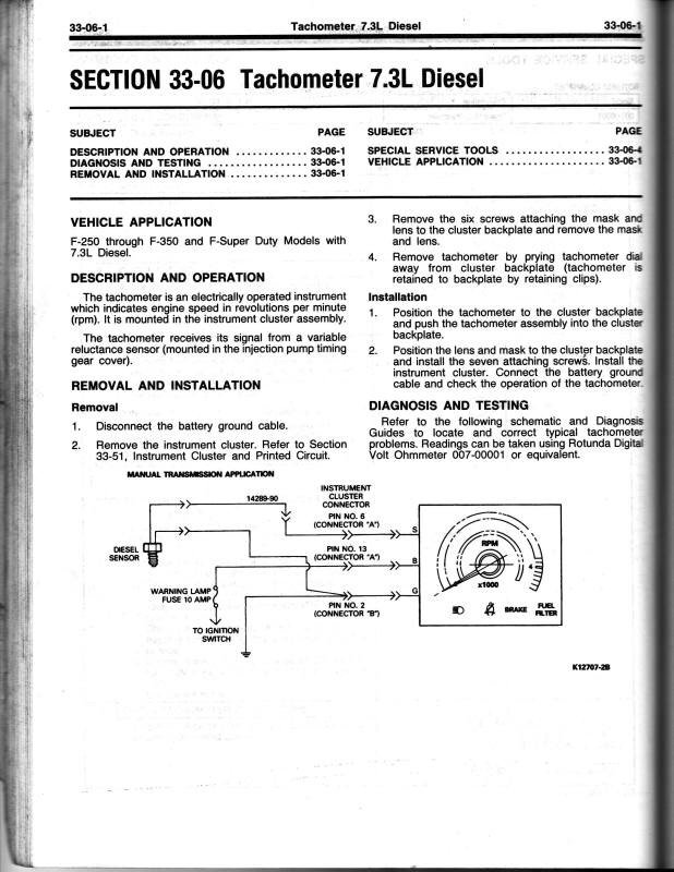
Isspro tachometer wiring diagram. Isspro ev2 gauge installation page 5 of 6 toll free sales customer service. Isspro pyrometer wiring diagram wiring diagram is a simplified tolerable pictorial representation of an electrical circuit. Pin 1 not used pin 2 redyellow. Connect the wires coming from the 3 wire cable as follows. Read wire to a fused ignition switched 12 vdc source. Interconnecting wire routes may be shown approximately where particular receptacles or fixtures must be upon a common circuit.
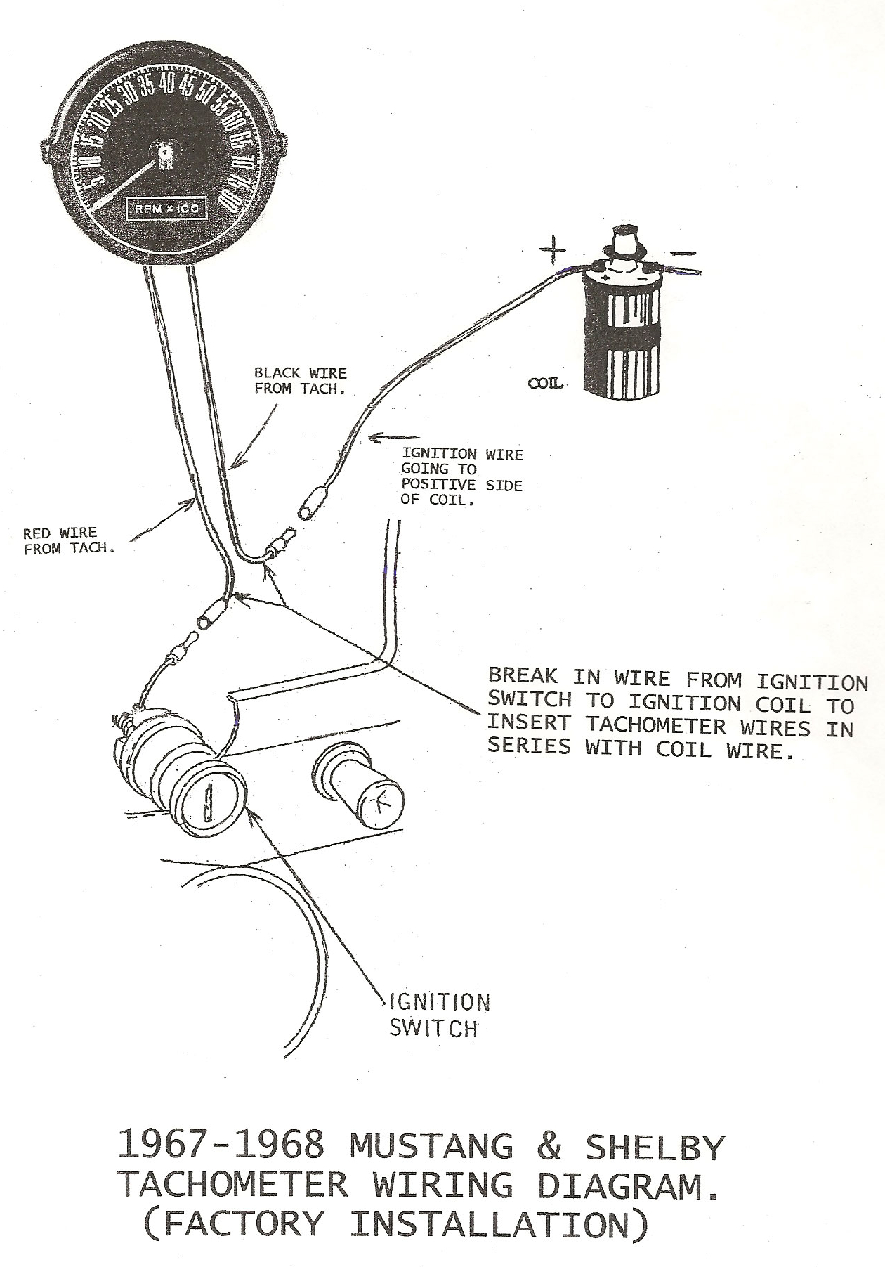
Also ground this connection as close as practical to the tachometer head. Connect to a clean ground such as a factory ground bolt. Connect the wires from the tachometer light as follows. Isspro tach wiring diagram wiring diagram architectural wiring diagrams perform the approximate locations and interconnections of receptacles lighting and enduring electrical services in a building. Black wire to the other sensor wire. Also ground this connection as close as practical to the tachometer head.
2 connect wiring harness to the vehicle as listed below. 5v output used if a speed sensor eg hall effect sensor requires a 5v source. 2515 ne. Connect the wires coming from the 3 wire cable as follows. 39 using the wiring diagram at the end of these instructions and the instructions that came with the gauges insert the wires into the isspro wire tool in the order they. Black wire to the other sensor wire.
It shows the components of the circuit as simplified shapes and the power and signal associates together with the devices. Red wire to a fused ignition switched 12 vdc source. If vehicle wire is not fused add a 3 amp in line fuse before the gauge. Whit wire to one of the sensor wires.
Gallery of Isspro Tachometer Wiring Diagram