We found out if we turned it off for a while it. 76 mm of wire through the opening.

C Wire Connection To L8148a Aquastat Doityourself Com
Honeywell chronotherm iii wiring diagram. 68 0057 chronotherm iii heat pump thermostats author. View and download honeywell chronotherm iii t8611g user manual online. It kept power off or said to replace batteries. Color coded 8 gauge thermostat cable with one conductor for each wiring terminal is recommended. Chronotherm iii t8611g thermostat pdf manual download. 69 0313 choronotherm iii owners manual.
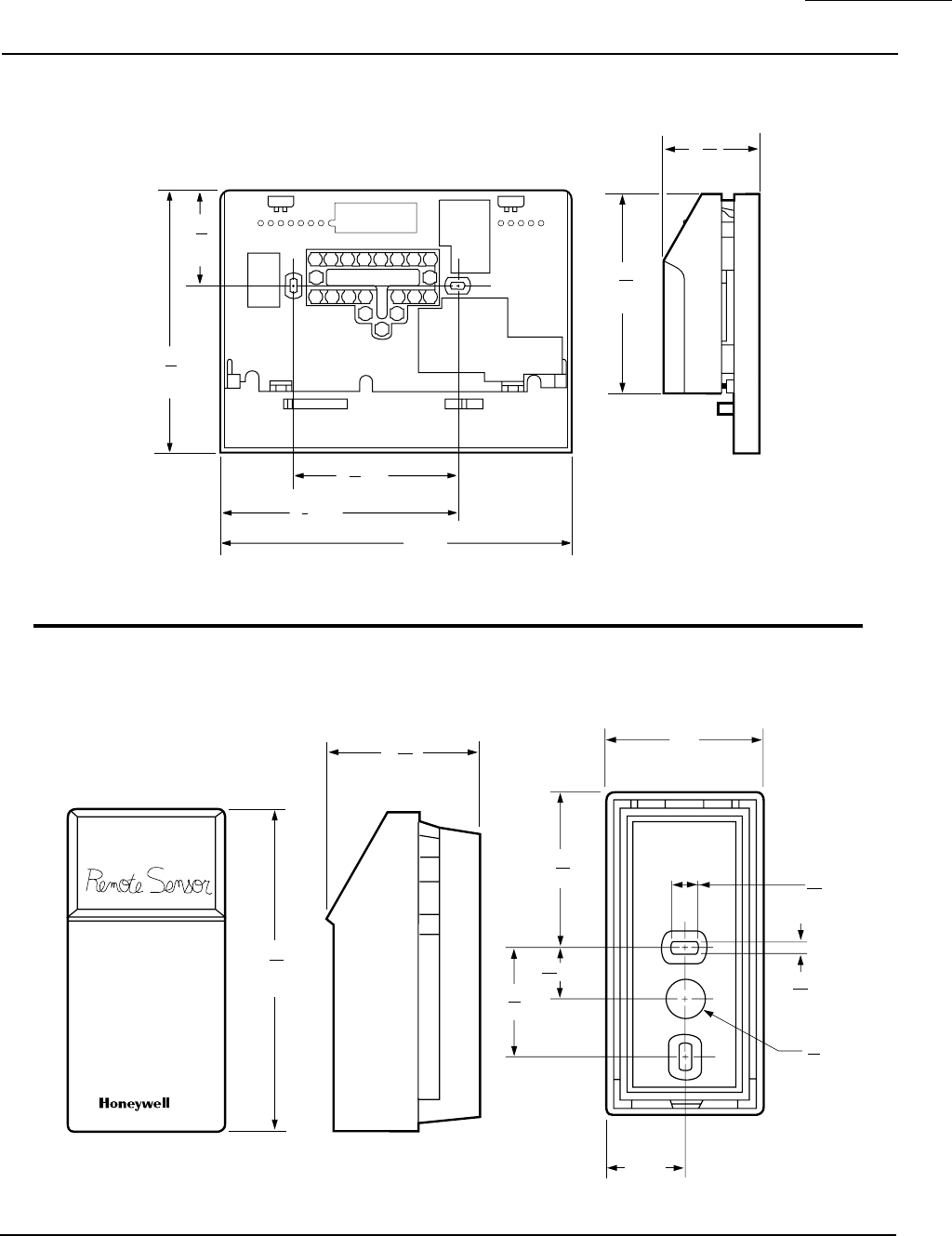
Page 3 t8602abcd and ts8602ac chronotherm iii fuel saver thermostats for straight heating only wallplate for wraparound insertion strip 716 in. I have the same issue of honeywell thermostat chronotherm iii tc. Letter or number on the wiring terminal as the wire is removed to avoid miswiring later. 69 0577 t8601c chronotherm iii zone thermostat author. Honeywell chronotherm t8600d product data. Chronotherm iii heat pump thermostats the t8611m chronotherm iii programmable thermostat provides automatic control of multi stage heat pump systems and offers users the highest standard of comfort and convenience available with energy savings.
Product data created date. 15 20 oct 05 old yeller was reincarnated as a thermostat. When you purchased your new honeywell chronotherm ill thermostat. Our page top sketch courtesy of honeywell controls illustrates the wiring diagram for a traditional honeywell t87f thermostat used for 2 wire single pole singlei am trying to wire an rth series honeywell thermostat and i followed what i believe is the correct wiring diagram but nothing is kicking on. Different sched ules may be selected for every day. Its the smart thermostat that.
Honeywell helping you control your world 69 0313 1 sm. Injunction of two wires is generally indicated by black dot at the junction of two lines. Installation instructions created date. But it doesnt mean link between the wires. Full seven day program capability. Keeps you comfortable by automati.
According to earlier the lines in a honeywell chronotherm iii wiring diagram represents wires. 8 mm restrict wiring to this area valve relay front view of terminal area wiring to be below top surface hot. Occasionally the cables will cross. If new installation run a cable to a hole at the selected wall location and pull about 3 in. Hbc technical communications subject. 11 mm strip 516 in.
Honeywell ecc technical communications subject.
Gallery of Honeywell Chronotherm Iii Wiring Diagram