T w 6. It reveals the components of the circuit as streamlined shapes as well as the power as well as signal links in between the gadgets.

Jogging Operation For Dc And Ac Motors
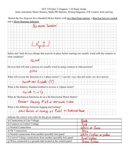
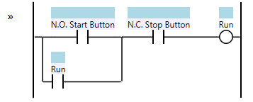
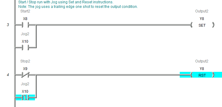
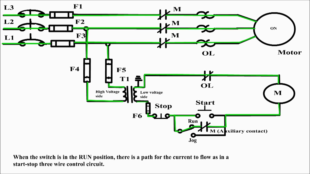
Start stop jog wiring diagram. Otherwise the structure will not function as it ought to be. The jog circuit in configuration 1 operates as follows. Typical wiring diagrams for push button control stations 7 start stop control wiring diagrams single station with motor stopped pilot light l1 start l2 i 1 stop 2 oi 3 n wol. Motor starter wiring diagram start stop motor starter wiring diagram start stop every electrical arrangement is composed of various distinct pieces. You can see that the diagram will work the exact same as the circuit above with the start and stop pushbuttons. Adding a jog input to the hard wiring diagram will look something like this.
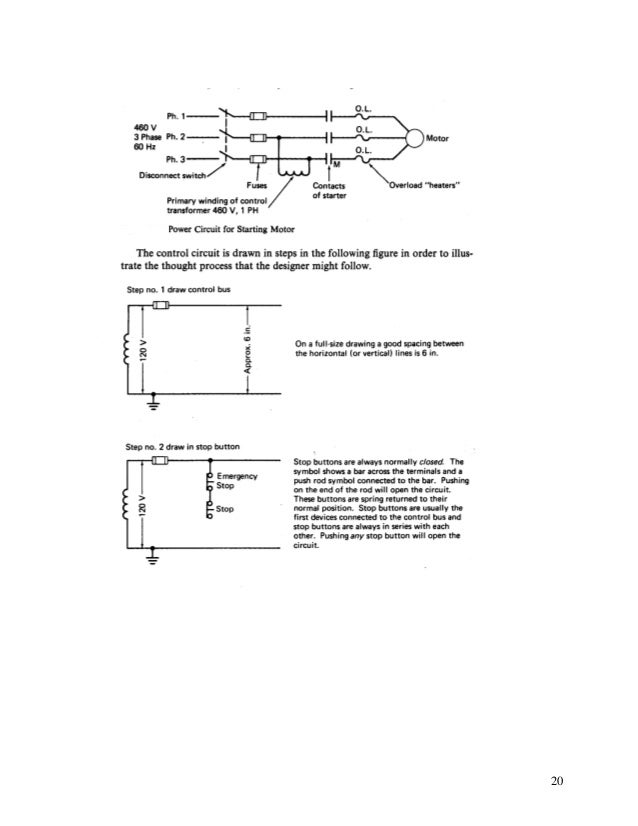
Pilot light l2 4 2 3 pilot light start stop bulletin 1495 normally closed auxiliary contacts are required. A wiring diagram is a streamlined conventional photographic representation of an electric circuit. The jog when pushed will break the sealing contact and then make a bypass of the start pushbutton. Collection of start stop wiring diagram. This video is a step by step explanation of wiring start stop basics. Each component should be set and linked to different parts in specific manner.
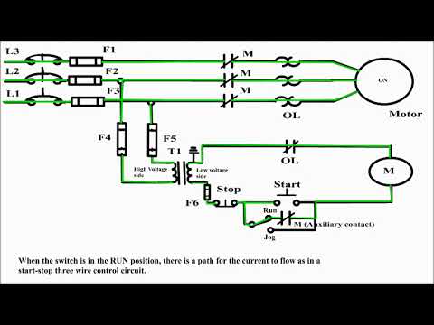
C i m nc. A switch is wired in series with the seal in of the pilot device. As long as you follow the ladder diagram and take it one wire at a time its simple. With the switch closed the control circuit acts as a normal stopstart station controlling a load connected to the pilot device power is sitting on the start and seal. This is the first of many motor control.
Gallery of Start Stop Jog Wiring Diagram