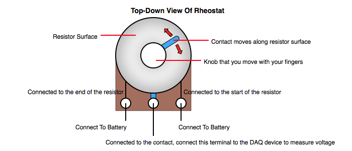
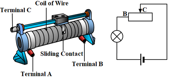
A 12 volt rheostat is a coil of resistance wire with a contact that can slide across the coil. This forms a variable resistor.

Alternator Charging System
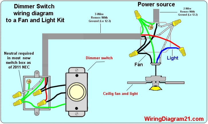
Rheostat wiring diagram. Rheostat circuit diagram. Trailer wiring diagrams showing you the typical wiring for most single axle trailer and tandem axle trailers. A device like this should only be used with an incandescent light fixture. From 4 pin flat to 7 way round connectors. A rheostat or dimmer makes it possible to vary the current flowing to a light fixture thereby varying the intensity of the light. 3 way switch wiring wire switch electrical code electrical wiring diagram electrical outlets overhead lighting dim lighting bobs video.
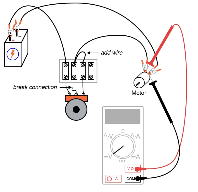
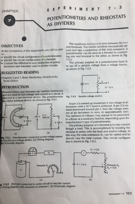
Potentiometers find their most sophisticated application as voltage dividers where shaft position determines a specific voltage division ratio. Connect the second wire to one end of the long spring. Wiring diagram for a rheostat dimmer. Lets get to know that in the next section. Connect the wires onto the open ends of both the batteries. In a circuit diagram a rheostat is often represented as shown below.
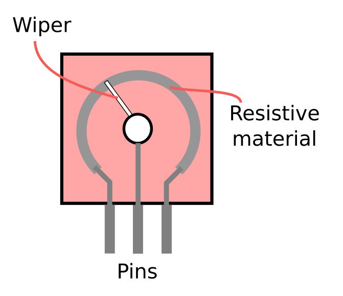
Hence wire wound resistors are mostly used for the construction of rheostats. These types of resistors usually have two or three terminals. Dimmer switch wiring diagram. Depending on where the contact is along the coil the resistance between the contacts will be different. For the units with three. The end of one wire must be connected to the bulb socket with the bulb in it.
The dimmer switch will have stranded wires that must be sliced to the solid cable wiring in a pigtail fashion. So on what basis does the rheostat work. Wiring illustration for using a potentiometer as a rheostat. Instructions for potentiometer wiring. Using a wire cutter cut the wire in equal lengths. One wire should be at least 8 centimetres long.
Working principle of a rheostat.
Gallery of Rheostat Wiring Diagram