This is because the lock mechanism requires power to disengage the latch so the door can be opened. In the case of a fail secure electric lock the door will remain in a secure condition when said power disappears.

Fail Safe Vs Fail Secure When And Where To Specify
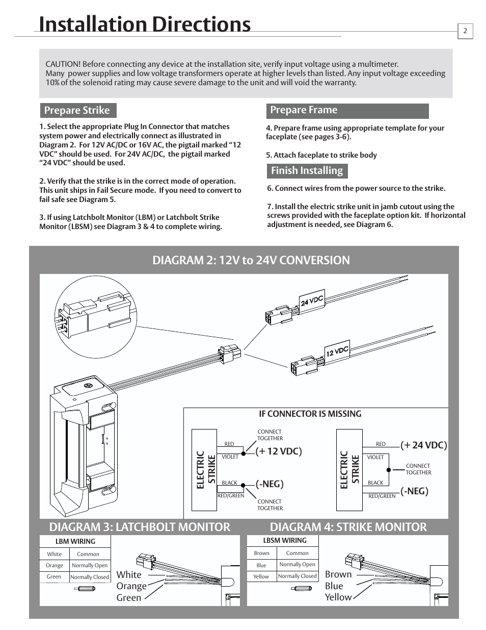
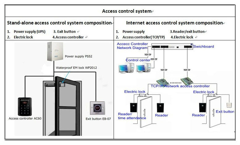
Fail secure strike wiring diagram. Quote request form. The von duprin 6300 surface mounted electric strike is only available as fail secure. The sdc acm 1 access control module is an magnetic lock or electric strike. An understanding of basic wiring diagrams fail safe and fail secure. The door strike maglock must not share power with the actatek. 1 based on the requirements the of additknal relay may be required for lock 2 if means of egress additional components may access control panel.
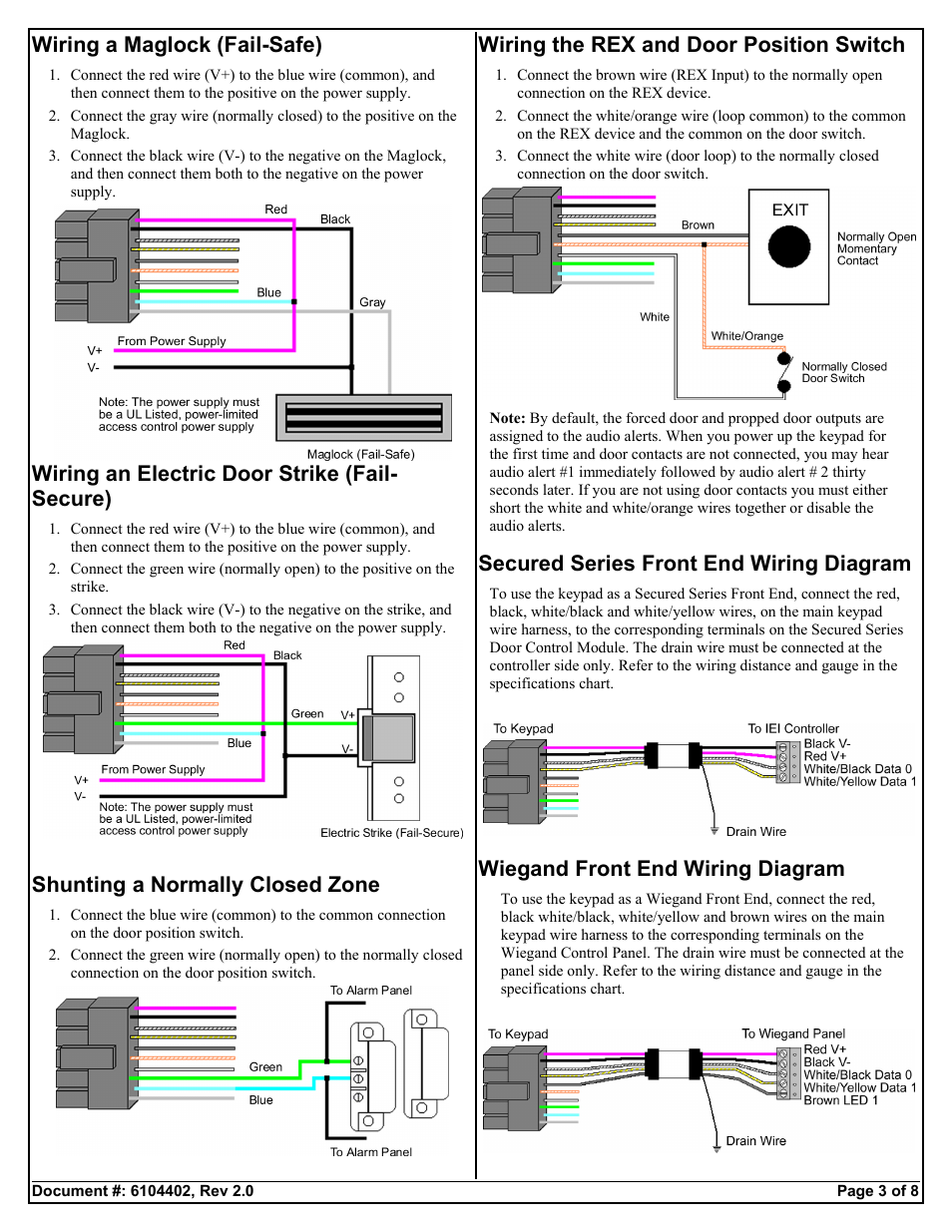
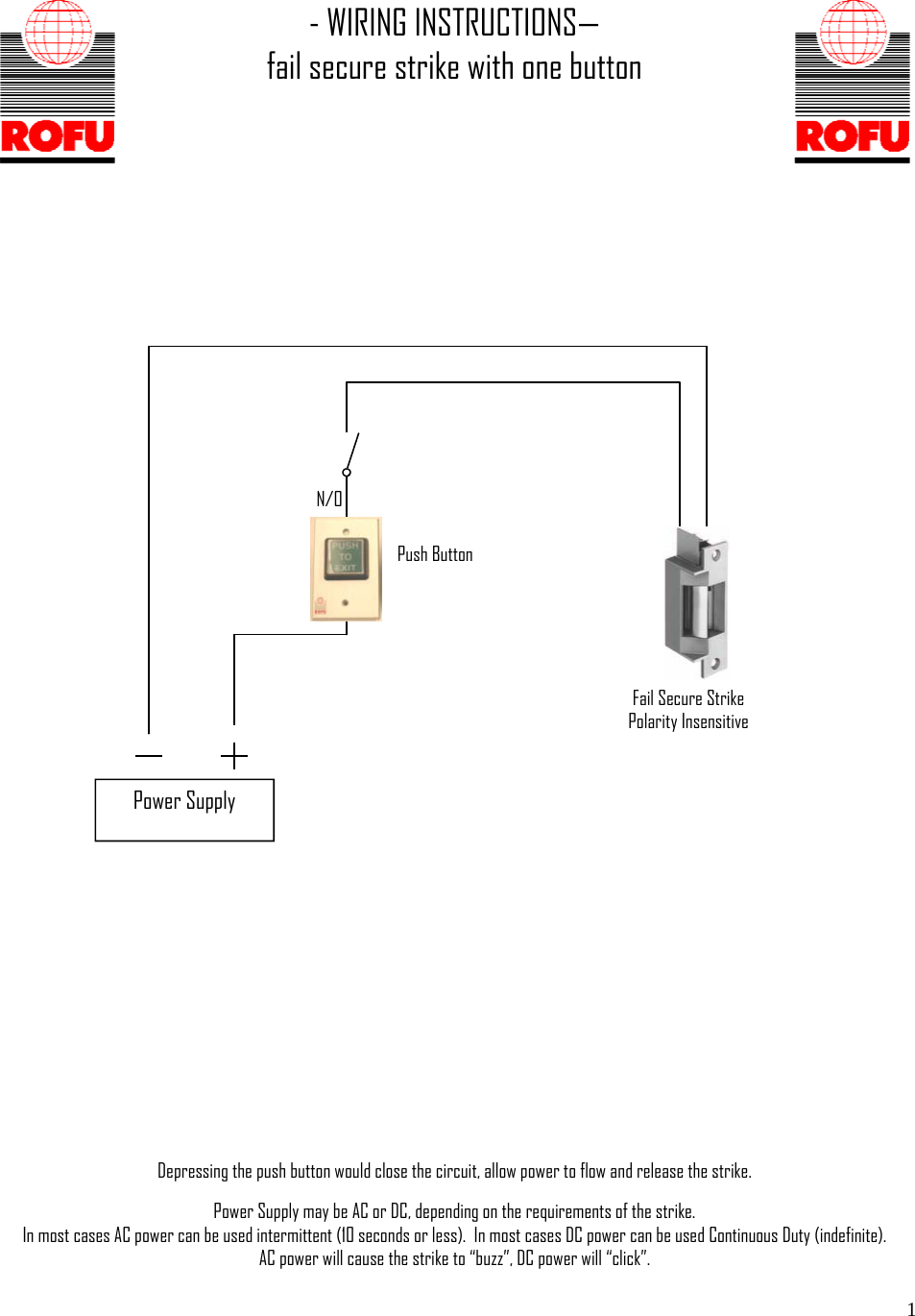
Electric door strike wiring diagram. For a fail secure system the default state is locked or secured. Common wiring d. Wiring instructions fail secure strike with one button power supply push button no fail secure strike polarity insensitive depressing the push button would close the circui t allow power to flow and release the strike. Fail secure solenoid connector strike voltage adaptor cable wire color see table below monitored version only 91 0098 for wood door applications spacer assy optional kit pn wdc7400 shim kit pn 91 0933 typical electric strike wiring diagram intermittent duty fail secure 24 vac control switch no ex. For two door or tamdem applications.
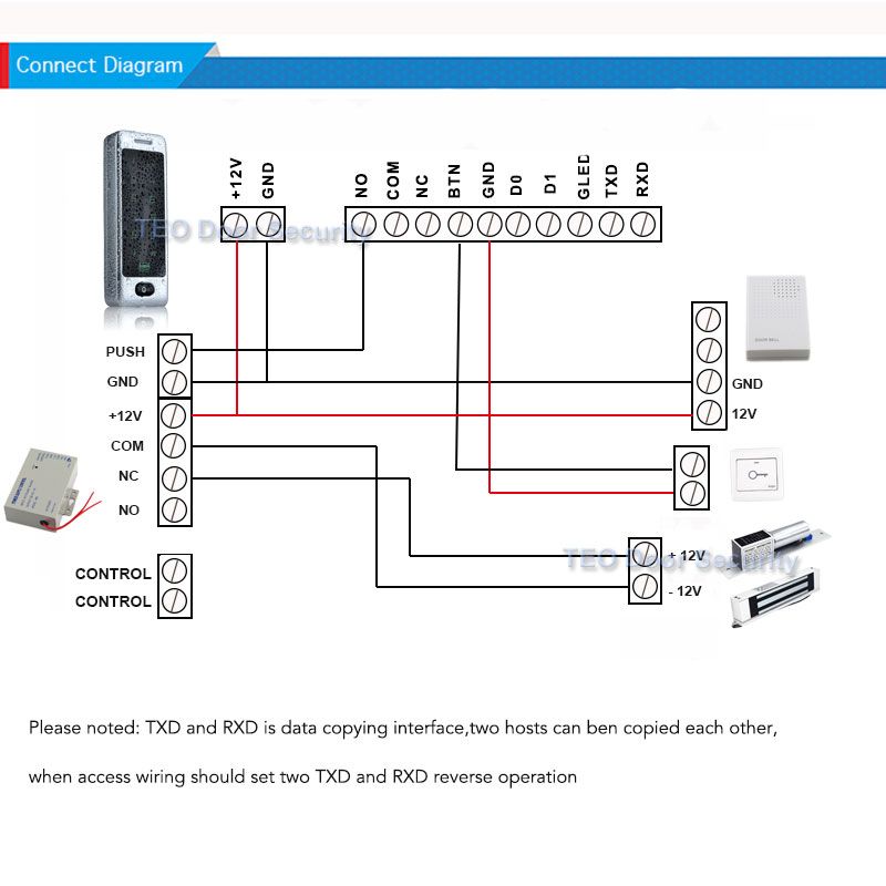
Sample wiring diagram for fail secure electric strike power supply electrical breaker panel supply and to fail secure electric strike control. Basic definition and facts about fail secure electric strikes. So with a fail secure system the door remains locked unless it is manually overridden. 1 spdt voltage output. A fail safe lock on the other hand allows the occupants to readily open the door because its locking mechanism requires power. Pushbutton keypadcard reader control.
Common wiring diagrams. Electric strike fail safe or fail secure. Wiring diagram nd lock. The next step is to have a fail safe method of cutting the power to the lock to ensure the where access control equipment is fitted to a fire escape door which includes an wiring break glass units and fire alarm interfaces the fib provides a switching. The following common wiring diagrams are availableone single door with panic barelectric latch retraction with auto operatordelayed egress fire. Unlike fail safe fail secure means that if the power is interrupted or fails the door stays locked.
Do not attempt to use the power supply. 7170 electric strike pdf 221 kb 7400 electric strike pdf 826 kb 7400 sub cover extension fitting instructions pdf 143 kb wirng diagram for 12 01 power supply pdf 34 kb wiring diagram for 12 03 power supply pdf 29 kb wiring diagram for 1225 power supply pdf 34 kb fail secure to fail safe pdf 241 kb. Electric door strike wiring diagram. Fast trac form. Mag lock panic. Power supply may be ac or dc depending on the requirements of the strike.
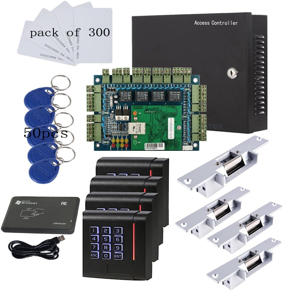
Actatek supports 12vdc door strikes maglocks with a maximum current draw not exceeding 1amp. Riser drawings for auto operators.
Gallery of Fail Secure Strike Wiring Diagram