No further than 20 feet from the outside of the pool wall. 1 pool pump receptacle outlet and wiring method a.

Swimming Pool Tips Amp Reviews Controlling A Salt System Or
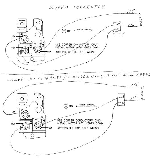
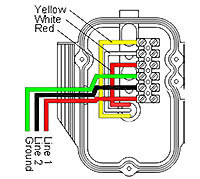
Pool pump wiring diagram. Sizing the circuit wiring for a pool pump. Hayward super ii pool pump wiring diagram wiring schematics diagram hayward super pump wiring diagram 230v. It shows the components of the circuit as simplified shapes and the talent and signal connections in the midst of the devices. Connect an 8 gauge wire to the metal posts of the pool the pump and the metal plate on the skimmer and then wire that to the pump to bond the entire pool. Century 1081 pool pump wiring diagram wiring diagram is a simplified conventional pictorial representation of an electrical circuit. Wire the twist lock receptacle.
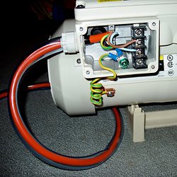
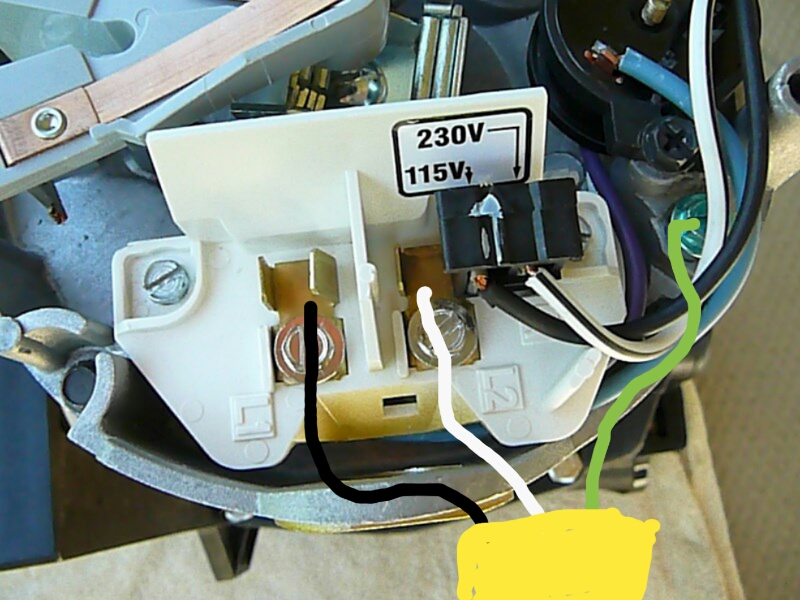
Convenience receptacle outlet must be gfci ground fault protected. A wiring diagram is a streamlined traditional photographic representation of an electric circuit. What is the size of the pump and the amperage and voltage circuit requirements. Variety of hayward pool pump wiring diagram. When wiring a single speed pool pump motor of either voltage 3 wires bring power from the breaker timer or switch and connect to the terminal board of the motor. The green ground wire connects to the green ground screw and the other two power leads will connect to the two power terminals marked usually l1 and l2.
Many pool pump motors use a thermal overload protector that prevents the motors windings from overheating. Plug in the pool pump and cover it with a weatherproof cover. Convenience receptacle outlet shall separate from the pool pump receptacle wiring. Wiring diagram includes numerous comprehensive illustrations that show the relationship of assorted items. Maximum flexible cord length for pump is 3 ft. Can be existing andor wired with any approved wiring method see diagram 2 2a b.
Receptacle must have a weatherproof cover that can be closed when the cord is. It reveals the components of the circuit as streamlined shapes and also the power and signal links in between the tools. December 22 2018 by larry a. The pool timer acts like an automated switch. With the main service off to the house wire in gfci circuit breakers to the electrical panel. Here are some factors that must be considered to properly determine the circuit wiring for a pool pump and pool equipment.
Identify the pool equipment. It includes directions and diagrams for different types of wiring methods and other products like lights windows etc. Will there be one circuit or more circuits. Most pool pumps use a 220 volt capacitor start induction run csi electric motor wired directly to a pool timer through a flexible conduit or whip. If a pump motor receptacle is located between 6 10 from the inside pool wall the receptacle must be a single twist lock outlet grounded and gfci protected.
Gallery of Pool Pump Wiring Diagram