Actuators may be connected in. View online or download belimo lmcb24 sr t installation and operation manual.
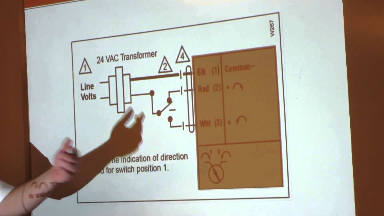
Belimo 101 Video 8
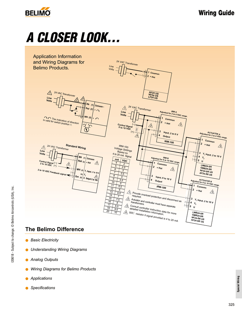
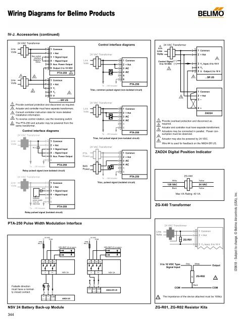
Belimo lmb24 sr wiring diagram. Lmb24 3 s auxiliary switch adj. Actuators shall be as manufactured b y belimo. 0 to 100 spdt 3 a 05a at 250 vac weight 14lbs 06 kg lmb24 3 p10 t electrical connection screw terminal for 26 to 14 ga wire feedback 10 kω 1w potentiometer lmb24 3 p5 t bulk pack only feedback 5 kω 1w potentiometer housing nema 1ip20 lmb24 3 t. Wiring diagram 1 2 3 24 vac transformer blk 1 common red 2 hot wht 3 y input 2 to 10v org 5 u output 2 to 10v line volts 2 to 10 vdc control signal 1 2 3 provide overload protection and disconnect as required. Actuators may be connected in parallel. Wiring diagrams installation notes provide overload protection and disconnect as required.
Actuators may also be powered by 24 vdc. When using lmb24 sr actuators only use acces sories listed on this page. Only connect common to negative leg of control circuits. 2 caution equipment damage. Power consumption and input impedance must be observed. Lmbx24 sr t proportional non spring return 24 v for 2 to 10 vdc or 4 to 20 ma wiring diagrams 1 provide overload protection and disconnect as required.
Variety of belimo lmb24 3 t wiring diagram. Lmb24 srlmx24 sr lmb24 sr1 bulk lmb24 sr tlmx24 sr t lmb24 sr t1 bulk. It reveals the elements of the circuit as streamlined shapes as well as the power as well as signal connections between the tools. Belimo lmcb24 sr t pdf user manuals. A wiring diagram is a simplified traditional pictorial depiction of an electrical circuit.
Gallery of Belimo Lmb24 Sr Wiring Diagram