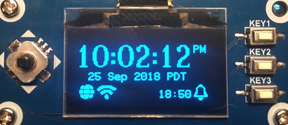
3 38 clock wiring 1 always disconnect the ground lead from the vehicle battery before wiring any gauge. Daylight savings time data entered from keyboard makes future dst changes quick and easy 2 line 16 character liquid crystal display lcd the ap22 is a two circuit calendar programmable solid state time switch.

How To Wire Pin Timers
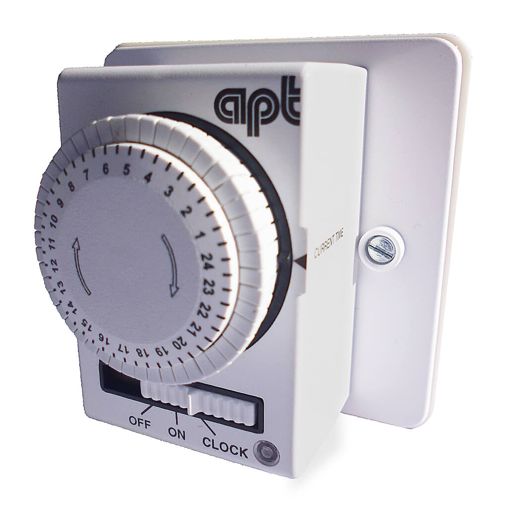
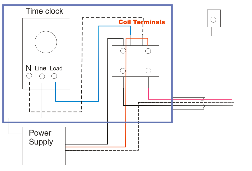
Apt time clock wiring diagram. The unit has electro mechanical operation and features a rotary dial with easy to set tappets that activate switching at pre set times. Whirlpool freezer plug wiring. Methods to save energy. Methods that show how to start saving energy right away for very little investment compared to the savings you will realize. A contactor will have two connsctions with either screws or terminals for spade adaptors and are most always marked coilthis will be where you install the control wiring from the time clockinstall the load wire from the time clock to one side of the coil and the neutral wire to the other side of the. 2 connect a constant 12vdc source to terminal 3 on the back of the clock.
Wiring an apt electromechanical timer. Wiring a light switch diagram 1. Housed in a flush mount case and ideal for private houses hotels leisure centres restaurants offices sheltered housing and schools. 5 connect both yellow wire leads coming from the back of the clock to the two wires from the time set pushbutton. More about wiring a water heater timer and energy savings for the home. How to wire a switch.
Toolbox 3 jun 2020 in forum. 2 aerian ie allsync master installation operation manual american time 140 3rd street south po box 707 dassel mn 55325 0707 phone. Discussion in electrics uk started by soloheadbeg 5 mar 2011. An immersion heater time switch with onoff and clock operation. Time clocks are marked for line and load. 4 connect dash light power to terminal 7 on the back of the clock.
It is used for switching electric circuits according to a pre set time and date program. Mattylad 4 jun 2020. Insert one bare end of the pigtail into the neutral screw terminal on the switch and tighten the screw. 14 feb 2011 messages. 3 connect a good ground to terminal 6 on the back of the clock. Summer time clock dial opening 91 s stop 1 hour boost timer start winter time water heater off peak o timed boost o economy 7 quartz 11 installation and connection should only be carried out by a suitably qualified person and in accordance with the current edition of the iee wiring regulations.
Wiring diagrams fully explained light switch. Cut an 8 inch length of white insulated wire as a pigtail then strip 12 inch of insulation from each end. The next step in wiring the time switch is to connect the neutral wires.
Gallery of Apt Time Clock Wiring Diagram