Diagram by tim dodge. Motorcycles 209k kit00056 box00019.

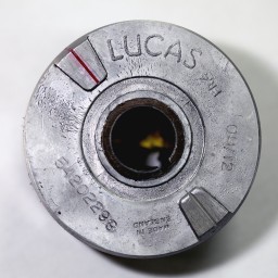
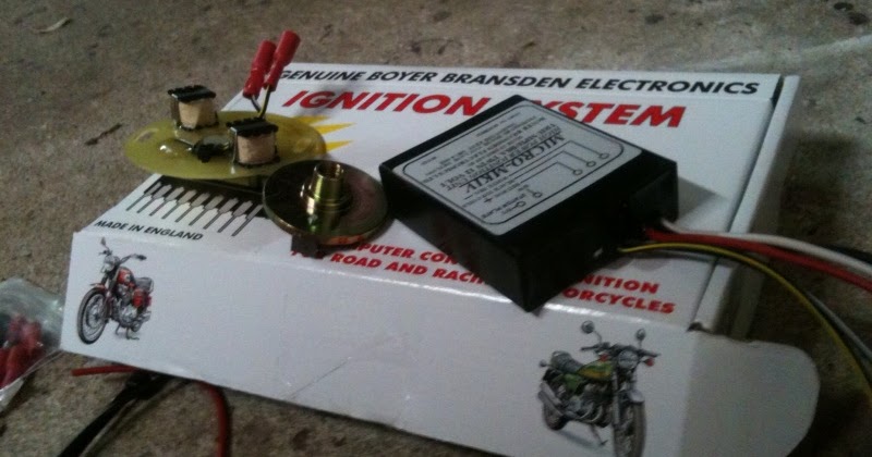
Bsa Twins Boyer Mk4 Ignition System 00052 1963 72 A50 A65t
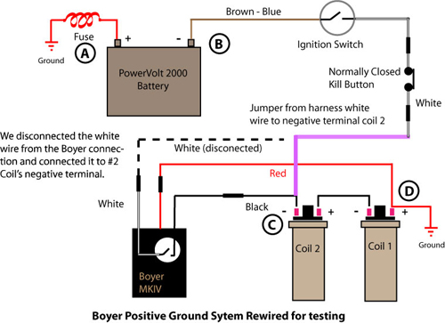
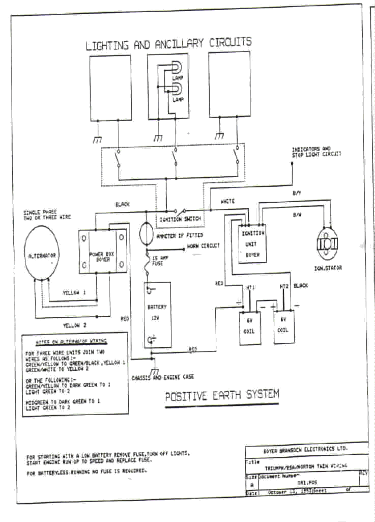
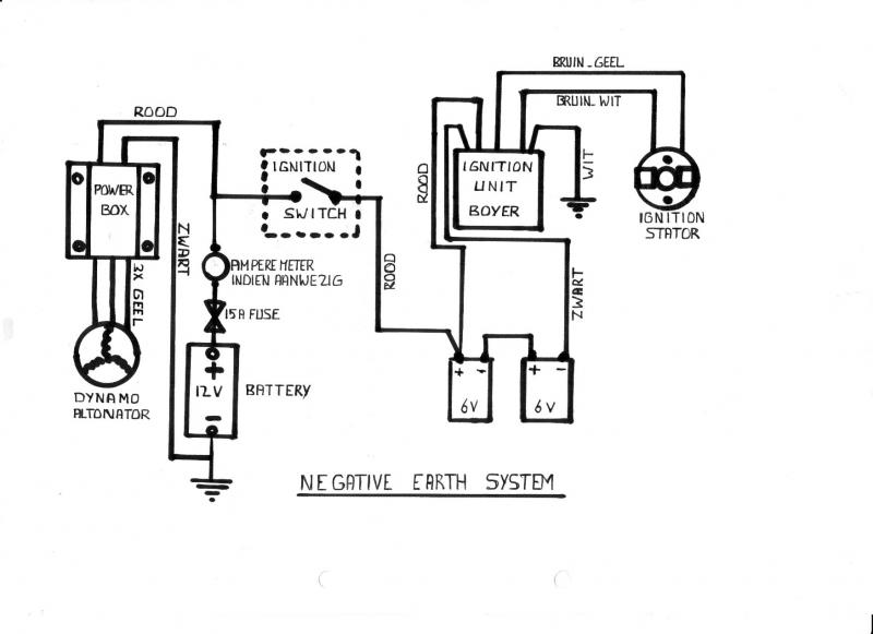
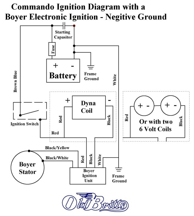
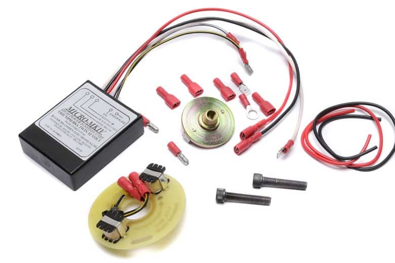
Boyer electronic ignition wiring diagram. The condition of the battery coils fuse holder wiring harness ignition switch kill button spark plug cables charging system etc. 16 it is essential that the existing electrical system is kept in good order ie. Micro mkivmkiii electronic ignition system for norton commando atlas. Battery ignition switch ignition coil ht. You can easily bypass the motorcycle feed hot and ground wires by running jumper wires directly from the battery to the ignition box. This diagram is not to be reproduced or used on any site without permission by rask cycle.
Apr 28 2017 wiring diagram for triumph bsa with boyer ignition. 19 connect the white blue wire the one removed from the ballast resistor to the white wire from the transistor box. Must be in good working order. Kit00054 box00021 micro mkivmkiii ignition for triumph trident t150 160 and bsa rocket three motorcycles. Do not assume engine is grounded to the frame and thus the battery boyer ignition and coils. Be sure you have the wiring diagram at hand and make the connections to the correct wires.
If the 12 volt ignition coils are stuck in their mountings apply penetrating oil and by removing the battery the coils can be reached from below and worked out. Many thanks to tim bondo bandit tech tips index. It is important to consider that just because your bike ran with a points ignition does not mean that it will run with an electronic ignition. Triumph wiring diagram switch furthermore camaro dash wiring diagram ignition. Wiring diagram for triumphbsa with boyer ignition. For mk3 commandos with a boyer ignition a power relay will help eliminate back firing since the boyer really likes 12v.
8 connect the red wire to the positive terminal of ignition coil no1. Kit00055 box00014 micro mk3 electronic ignition system for honda 4 sohc. This would not be needed for the power arc ignition since it will work down to 6v. Cable plug plug cap and associated wiring. Oct 14 boyer negative ground wiring diagram 97 ford explorer power window wiring diagram 91 toyota pickup wiring diagram audi a3 engine bay fuse box diagram broan exhaust light wiring diagrams 66 chevelle fuse block wiring diagram ballast resistor wiring diagram 83 silverado fuse diagram club car wiring diagram 48 volt 3 way momentary toggle switch wire diagram cycle 2 cycle si engine diagram. Click here for negative ground wiring diagram.
18 connect the black wire from the transistor box to the terminal of the right hand ignition coil. 15 if an old boyer bransden ignition unit is being replaced with a new one it is advised to recheck the timing using a strobe light. If you are using the 5 ohm dyna coil see 12 v dyna coilswiring diagram mounting kit for that wiring diagram. 7 remove the red wire going to the earthing terminal on the condenser unit. Power arc electronic ignition.
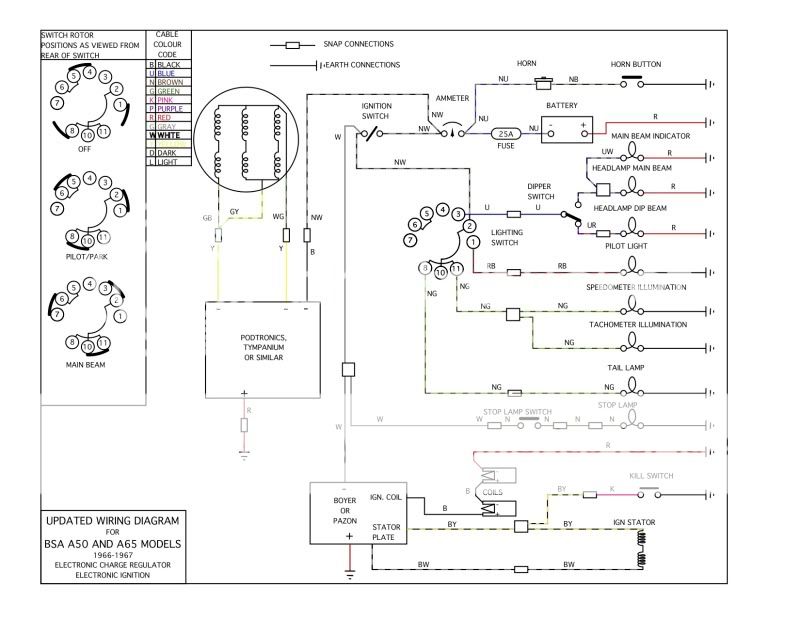
Gallery of Boyer Electronic Ignition Wiring Diagram