If the connection is required complete step 2. See the vehicle wire chart reference for wire colors step 6.
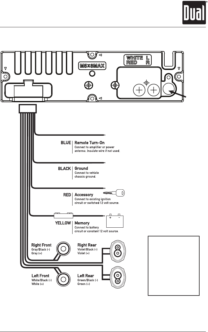
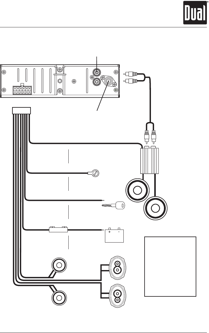
Page 3 Of Dual Car Stereo System Dcbt304u User Guide
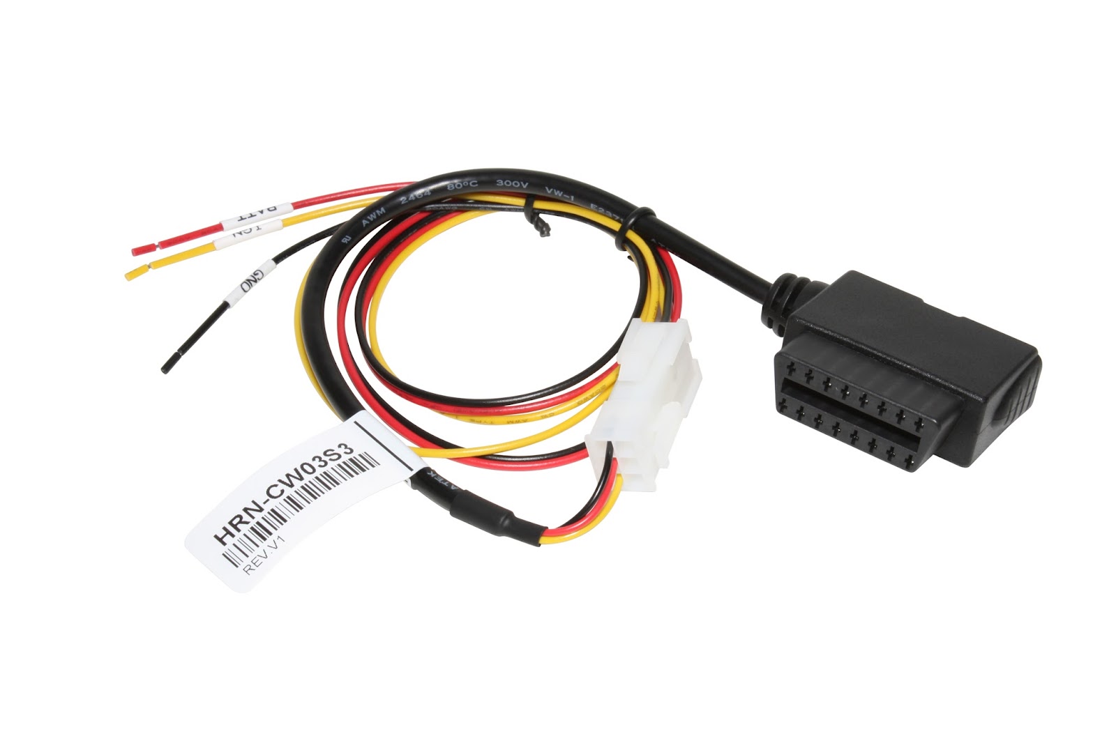
Hrn 3 wiring diagram. The lite plan hrn 3 emergency module invertor to run 1 lamp with a wattage between 4w and 36w. Go to step 3. Detecting ignition using the hrn cw03s3. The other side to terminals 34. See the vehicle wire chart reference for wire colors connect the yellowbrown wire of the ch1 t harness to the wire located at pin 14 of the obdii connector. Locate the swi 2 wire in the vehicle sync harness.
Vehicle specific amplifier replacement harness. Adapter harness needed in conjunction with hrn ds09t2 hrn dr09t2 or hrn gs09k2 on 2017 kenworth and peterbilt trucks for enhanced engine data support. This t harness connects to the factory amps input harness and supplies audio and databus signals to the. If an asset is installed with a go7 or newer device and is using the hrn cw03s3 with all 3 wires connected properly the device detects the ignition wire and uses it for ignition sensing. This idatalink harness connects a maestro ar amplifier replacement module sold separately to your toyota built vehicle so you can replace its factory amplifier with a more powerful idatalink ready aftermarket amp or a compatible processor. 63 cm 25 inches.
Disassemble the dashboard carefully and remove the factory radio from its housing without disconnecting it. We are the cheapest online dealer in the uk for this inverter module so look no further. Ads hrnav chr01 programmed firmware ads rrsr chr01 ds products required idatalink maestro rr radio replacement interface. This is a brand new replacement complete with 3 year warranty for peace of mind when purchasing from us. To test the swi 2 wire use a multimeter. Connect the redbrown wire of the ch1 t harness to the wire located at pin 6 of the obdii connector.
2010 june 2011 m37m56. Installation instructions 3 wiring diagram 5 vehicle wire reference chart 6 radio wire reference chart 7. The mains ballast connections are made to terminals 5 8 see typical wiring diagrams for details overleaf. A led indicator is provided to. If you do not plan to reinstall the hrn cw03s3 with a go 6 de pin or cut off the yellow wire of the hrn cw03s3. Horn hrn 3 wiring diagram c d e f g h i j k m a b hrn n o p wiring diagram horn wiring diagram infoid0000000006032449 jclwa4216gb revision.
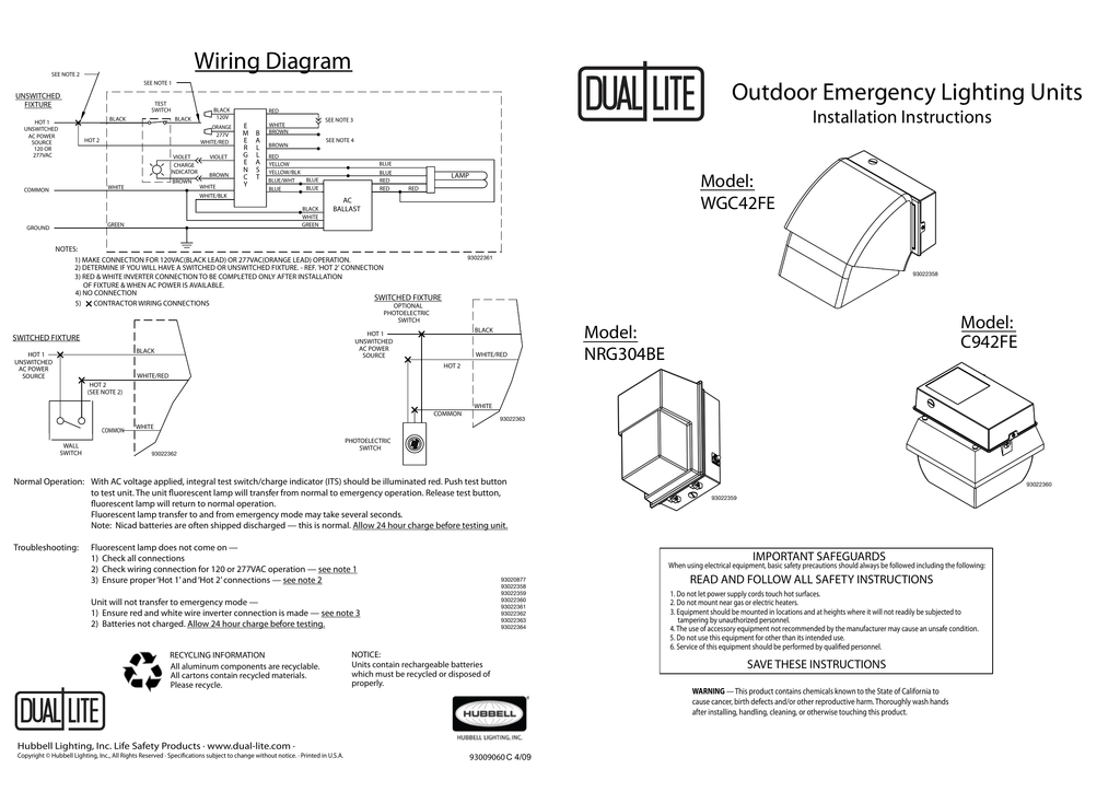
Under mains healthy input terminal 8 links to 1 7 to 2 6 to 3 and 5 to 4 then upon unswitched mains failure the inverter circuit powers the lamp from the battery. Hrn bs04a1 not required for go9. Its for the 2017 kenworth and peterbilt trucks using go7 and go8 devices. See the wire chart for vehicle wire colors and location.
Gallery of Hrn 3 Wiring Diagram