You can use a circuit tester to verify connections. If your vehicle is not equipped with a working trailer wiring harness there are a number of different solutions to provide the perfect fit for your specific vehicle.

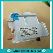
Sanyko Type Plastic Defrost Timer For Refrigerator Tmde706sc
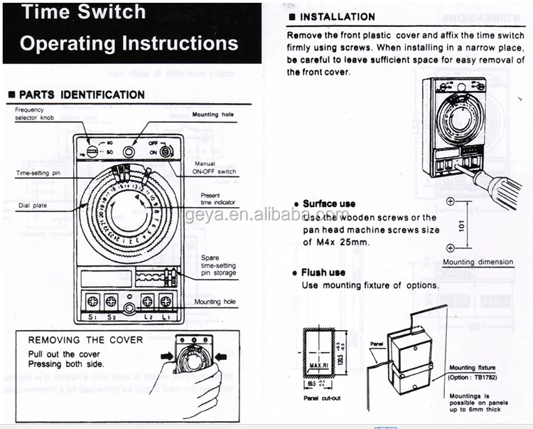
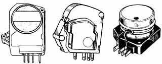
Tmde706sc wiring diagram. With the light at the beginning middle and end a 3 way dimmer multiple lights controlling a receptacle and troubleshooting tips. Test the defrost timer with a vom set to the rx1 scale. 4 pin trailer wiring diagram. Disconnect the wires from the timer and timer motor. To advance to the defrost. In this case very carefully bend terminals 2 4 3 as illustrated.
One ring video doorbelltwo internal doorbells. To connect the electric system of your trailer to the vehicle you will be using special connector. Single pole may sound simple but there are different ways to wire a single pole switch. How to replace an expensive adaptive defrost timer with a low cost manual defrost timer duration. Clip one probe of the vom to each defrost timer not motor wire and turn the timer control screw shaft until it clicks. Tmde706sc defrost timer this model timer can working for different type refrigerator tmde706sc 200 240v 5060hz 5a 7 hour and 25 minute voltage rating frequency incoming current input power load 3 2connecting defrosting loop 3 4connecting compressor ac200 240v 5060hz 15ma 18w15w 250v 5a 13hp ac100 120v 5060hz 25ma 18w15w 125v 10a 13hp ac127v 5060hz 20ma 18w15w 140v 10a 13hp.
Wiring diagrams for ring video doorbell setup if youre in the process of setting up multiple ring video doorbells internal doorbells and transformers the following wiring diagrams may help. Remove the timer from its brackets by backing out two retaining screws. State street appliance 28384 views. Switch wiring diagrams a single switch provides switching from one location only. Above we have describes the main types of trailer wiring diagrams. Check out or trailer wiring diagrams for a quick reference on trailer wiring.
Click on your setup to view the diagrams. The below information is for reference and is commonly used throughout the industry but can vary depending on who built the trailer. Use needle nose plier to hold the terminal while bending it with another plier. Each terminal is connected using a seperate wire. Below is the generic schematic of how the wiring goes. Wiring diagrams for 3 way switches diagrams for 3 way switch circuits including.
The power can come from either the switch box or the fixture box and a set of electrical switch wiring diagrams will explain each of these scenarios to you clearly. After the uet has been installed and power has been restored to the equipment the compressor cycle will be enabled. Complete with a color coded trailer wiring diagram for each plug type this guide walks through various trailer wiring installation solution including custom wiring splice in wiring and replacement wiring.
Gallery of Tmde706sc Wiring Diagram