Automatic water level controllers are a product that was created to automatically control a motor which helps to ensure a constant reserve of water in a storage tank. Use additional unions per figures 2 2 and 2 3.
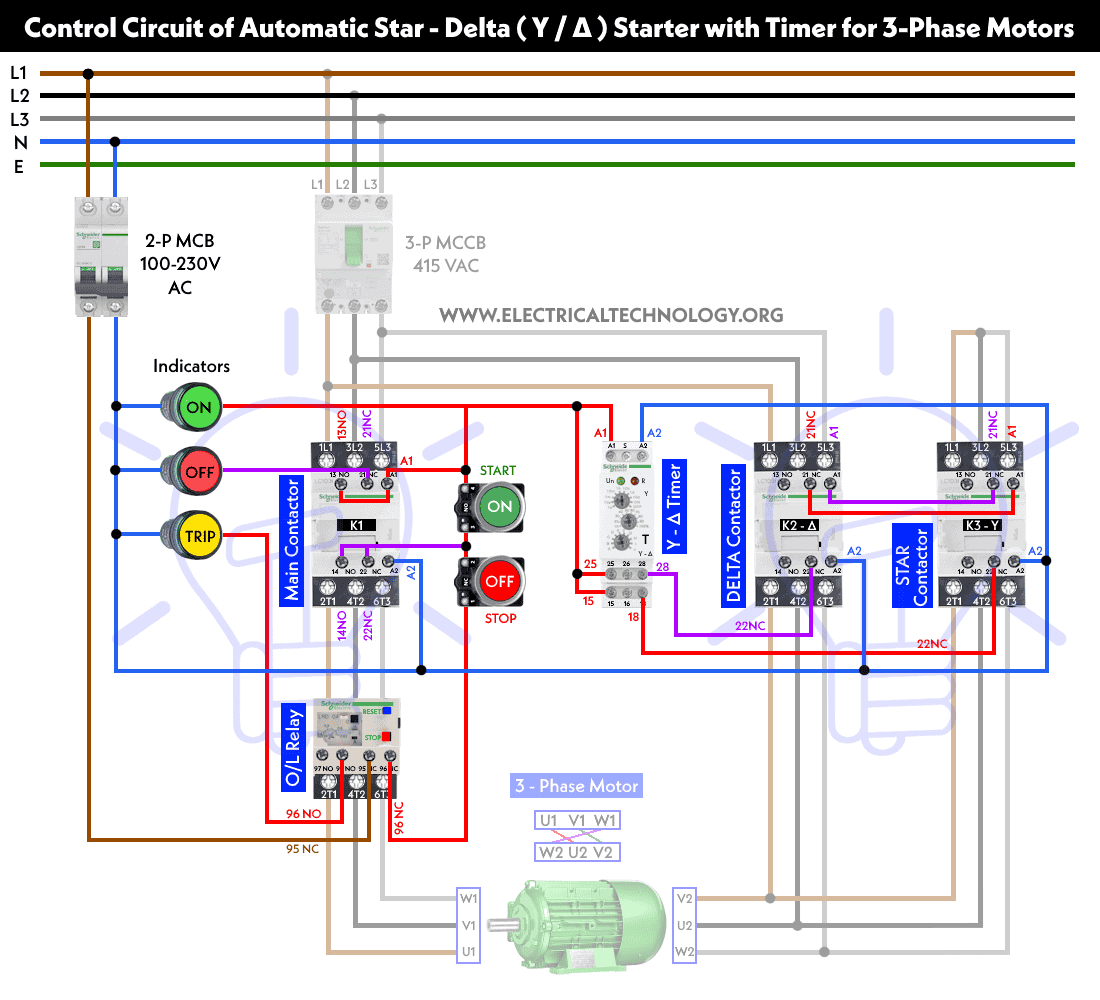
Star Delta Starter Y D Starter Power Control And Wiring
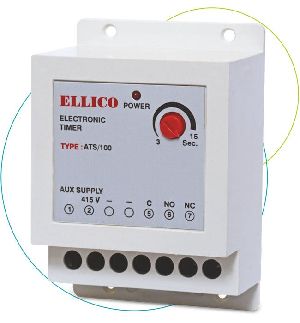
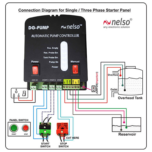
Ellico water level controller wiring diagram. At the end of video you will understand detailed water level controller installation. The installation must conform to local electrical codes. In the diagram a water level controller shown with motor starter water level sensor with over head tank and underground tank. Can run the motor manually and automatic using the switch. Here we have used bc 547 as a switch. To mount the panel use bracket pa rt number 8 3267.
Since 1983 general electronics controls is the pioneer and leader in the field of electronic control equipments under the brand name ellico which speaks of stringent quality control and aesthetic looks. Wiring diagram of a typical cemline stainless steel level controller sscm 2001 control module if you are replacing an existing cemline stainless steel level controller with a new unit consult the submittal sheet and cad. As a result transistor t1 gets forward biased and starts conducting. We have created three different levels of water level detection namely a b and c. Circuit diagram and explanation. Code compliance is the responsibility of the customer or customers contractor.
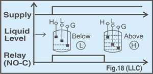
Since its foundation in 1983 with the aim to become market. Whenever water level reaches point a transistor q1 is turned on and red led starts glowing. Water level controller circuit water level controller circuit. When there is enough water in the underground tank probes c and s are connected through water. This is video is animation of water level controller connection and wiring diagram with float switch. This in turn switches transistor t2 on.
These automatic water level controllers are used to automatically fill the over head tank when it starts or has become empty as well as monitor the water level in it. As shown in the water level controller circuit given below ultrasonic sensor modules trigger and echo pins are directly connected to pin 10 and 11 of arduinoa 16x2 lcd is connected with arduino in 4 bit modecontrol pin rs rw and en are directly connected to arduino pin 7 gnd and 6. In the below diagram is about the water level controller. Drawing supplied with the original unit for specifications and exact wiring diagram. We have connected leds at three points to indicate particular water level along with a buzzer to indicate the full level of the tank. Of the controller water column level sensor and second the wiring of the controller and level sensor.
Inspiration and foresight are great for all business but to be able to see decades ahead is what separates some from most. Automatic water or liquid level controller wiring diagram. Since 1983 general electronics controls is the pioneer and leader in the field of electronic control equipments under the brand name ellico which speaks of stringent quality control and aesthetic looks.
Gallery of Ellico Water Level Controller Wiring Diagram