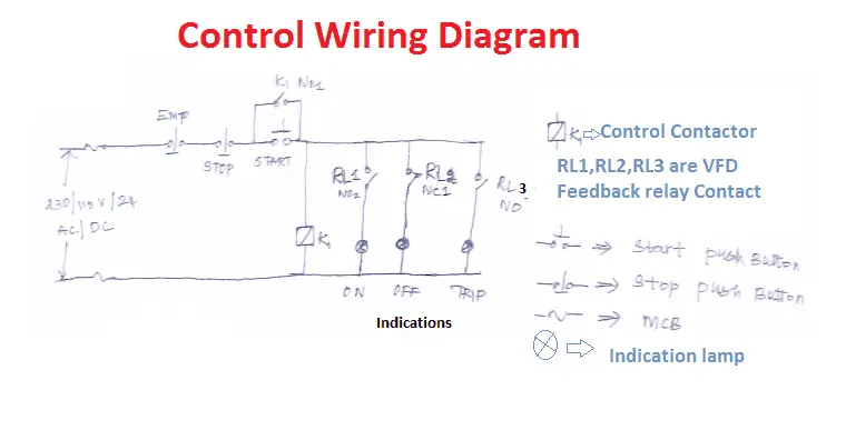
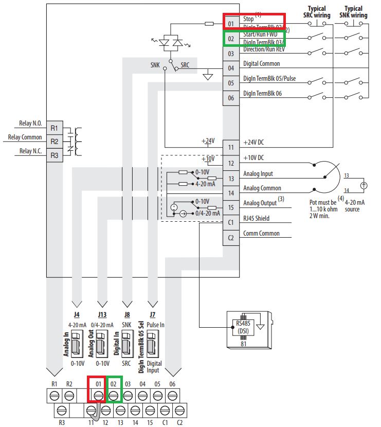
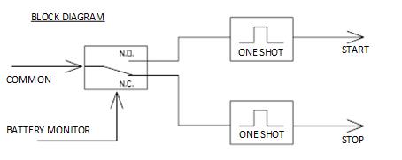
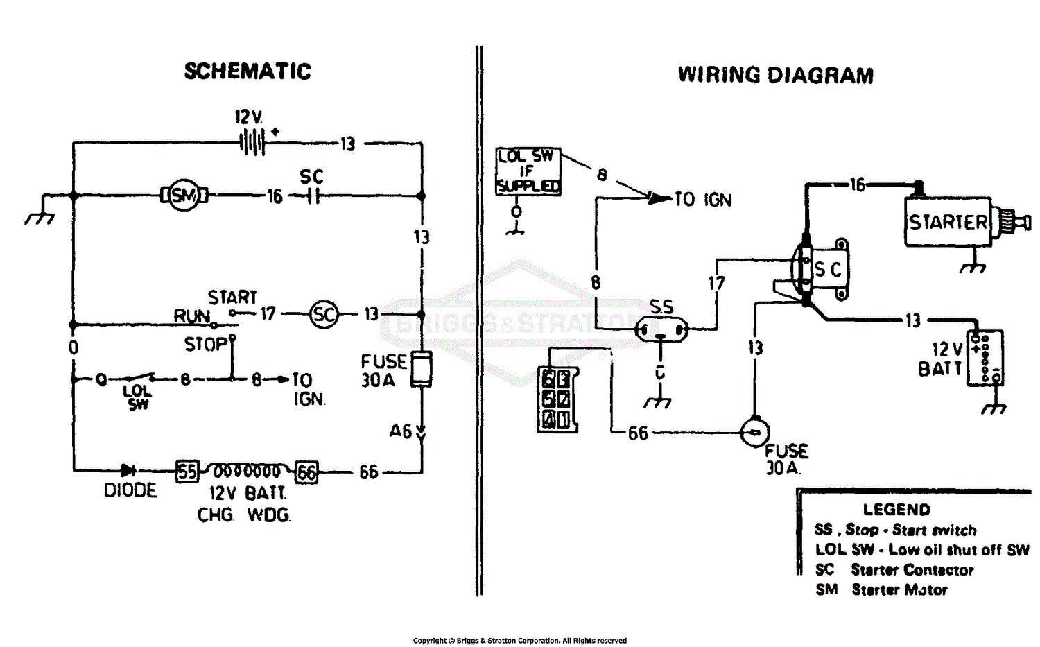
K1 no1 pb3 pb4 pb5 should be of potential free contact. It reveals the components of the circuit as streamlined forms and the power and also signal links between the gadgets.

Dont Know How To Wire A Start Stop Switch To Motor
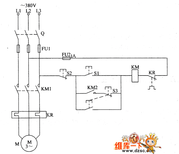
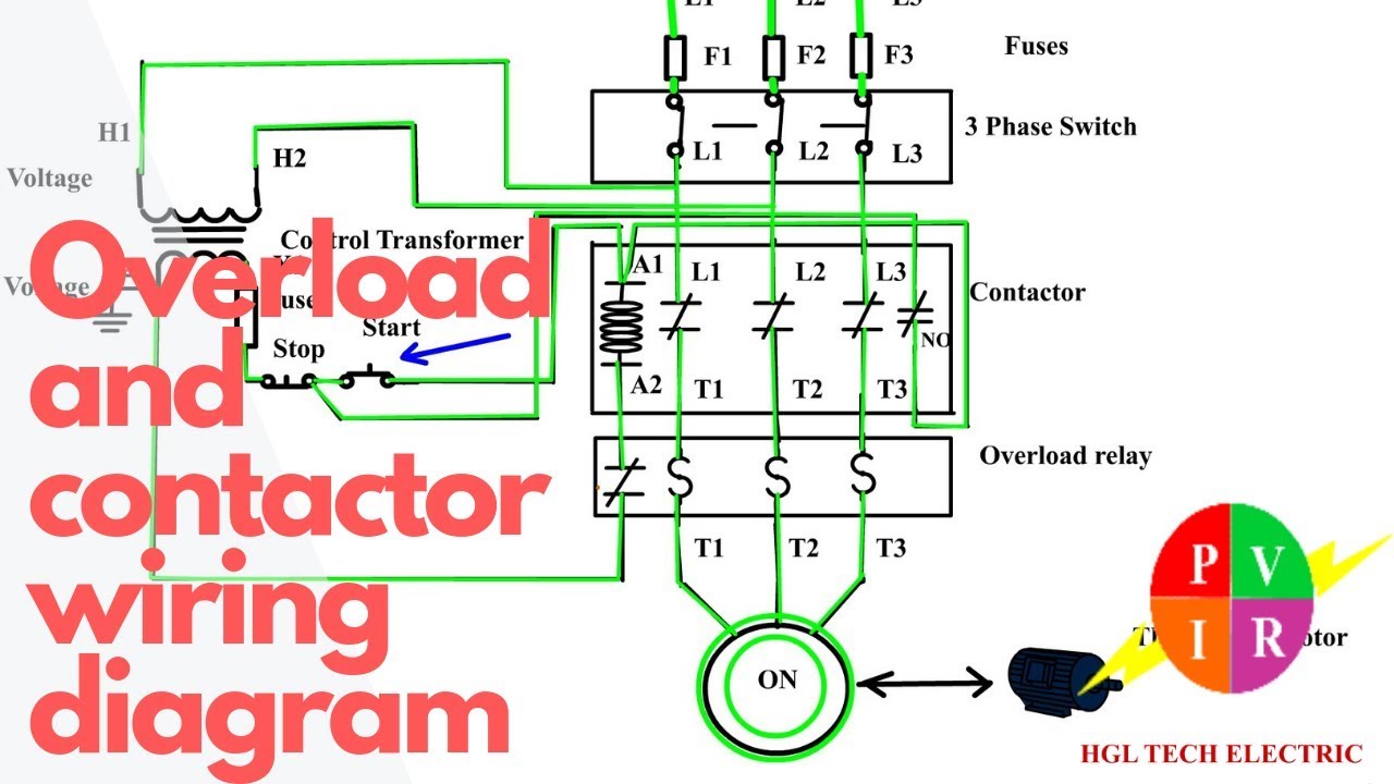
Stop start wiring diagram. Tmeelcsoftwiring how to connect the 3 phase controller or failure relay to main board wiring diagram. 1 j start 2 3 stop i no. It reveals the components of the circuit as streamlined shapes as well as the power as well as signal links in between the gadgets. Otherwise the structure wont function as it ought to be. Typical wiring diagrams for pushbutton control stations start stop control wiring diagrams single station basic circuit r 1 klai. Assortment of start stop wiring diagram motor.
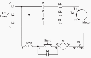
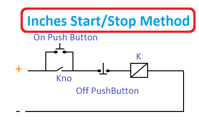
Each part should be placed and connected with other parts in particular way. Start stop push button wiring diagram emergency stop push button wiring diagram start stop push button station wiring diagram start stop push button switch wiring diagram every electrical structure consists of various different parts. When you press the on push k1 contactor will hold and k1 no1 become nc. A wiring diagram is a simplified standard photographic representation of an electrical circuit. Vfd start stop wiring diagram. I operation depressing the start button energizes coil m hold in contacts m and maintains the circuit after the start button is released.
Collection of start stop wiring diagram. Connect or do wiring as per vfd side drawing you take 24 v from the vfd pcb directly. I zl ii i i ii i i fo 0. A wiring diagram is a streamlined conventional photographic representation of an electric circuit.
Gallery of Stop Start Wiring Diagram