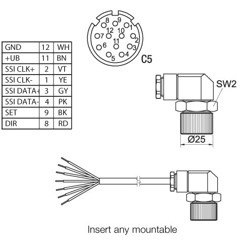
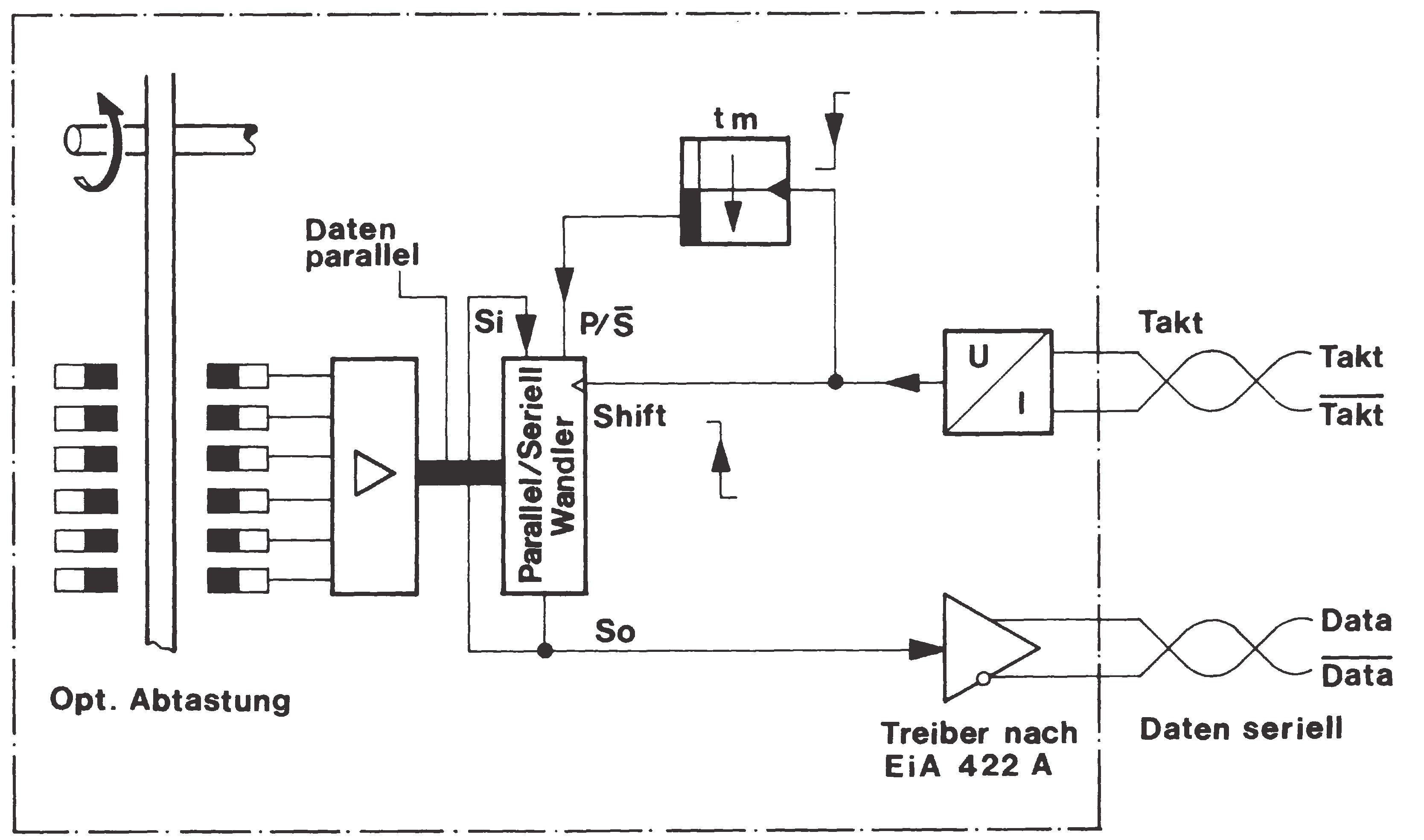
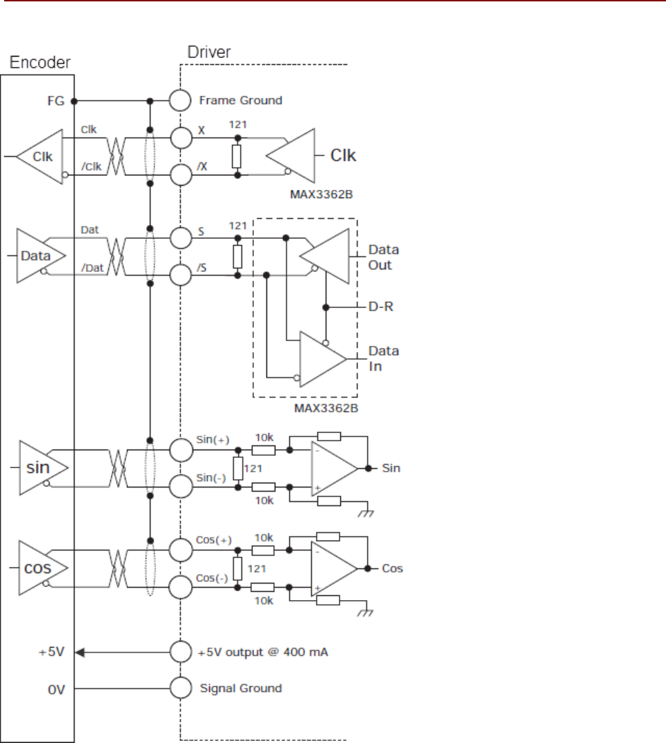
Page 24 wiring 31 ssi encoder signals block diagram you must ground the shields of the cables between encoder and technology module both through the shield support at the front connector shield bracket and terminal and at the encoder. The figure below shows the block diagram of the technology module with one connected ssi absolute encoder.

Rmc150 Ui O Wiring
Ssi encoder wiring diagram. Encoder ssi av1y 71 132ml 0 198 889 1 as7y2 71 132 1 362 159 9 1 362 192 0 av1y 160 225 0 198 889 1 ag7y2 160 225 1 362 210 2 1 362 164 5 absolute. It shows the components of the circuit as simplified shapes and the capacity and signal associates surrounded by the devices. Incremental encoders are available in two basic output types single channel and quadrature. Wiring of ssi depends on the variant of ssi protocol present. Ssi encoder wiring diagram calt hae18 12 bit hall magnetic angle rotary encoder ssi absolute. Wire draw encoders consist of a wire draw mechanism and an encoder.
Multi channel differential encoder wiring with commutation tracks can have up to 14 wires and miswiring can result in signal issues such as deformed pulses low signal amplitude and shorted connections. Wiring ssi encoder edit edit source. Ssi encoder cabling and data rate. Encoder wiring schemes can be unique to each encoder and one should follow the diagram or pinout designated on the encoder datasheet. However as clock frequency increases the maximum cable run decreases a limitation common to all protocols. A single channel encoder often called a tachometer is normally used in systems that rotate in one direction only and require simple position and velocity information.
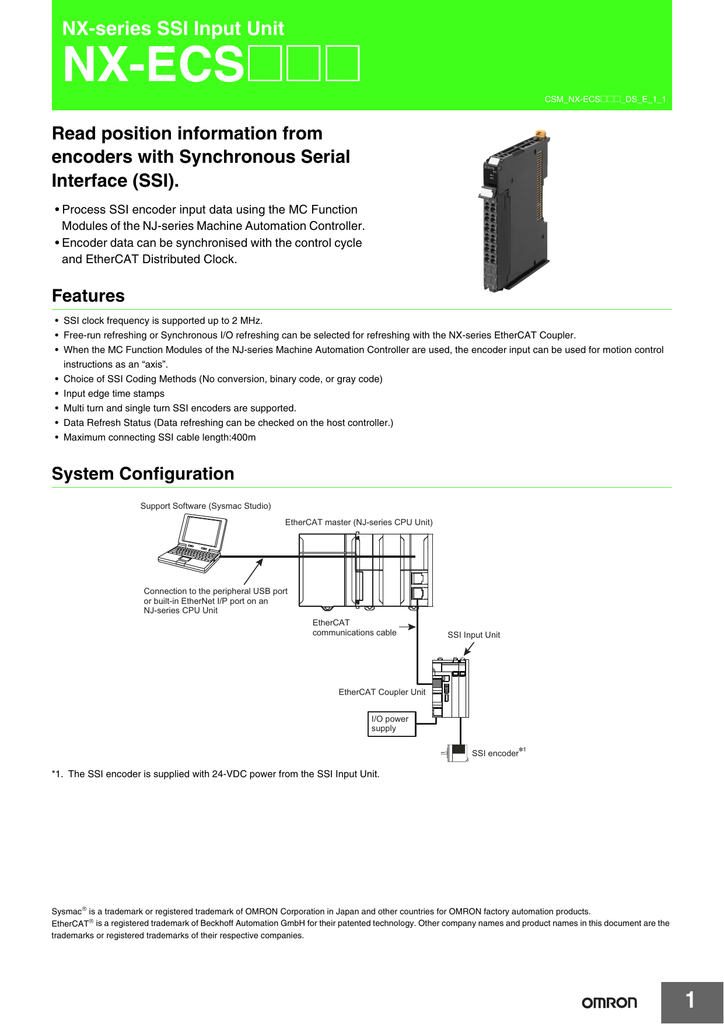
About the module the 1734 ssi module collects serial data from industrial absolute position encoding sensors that use a standard ssi protocol. Controller and a slave eg. Sicks wire draw encoders support a large selection of interfaces and facilitate easy system integration for applications in challenging industrial settings. Quadrature encoders have dual channels a and b phased 90 electrical degrees apart. Ssi is based on rs 422 standards and has a high protocol efficiency in addition to its implementation over various hardware platforms making it very popular among sensor manufacturers. Synchronous serial interface ssi is a widely used serial interface standard for industrial applications between a master eg.
The rotation of the drum which is proportional to the length being measured is recorded and output by an encoder. Ssi encoder wiring diagram wiring diagram is a simplified pleasing pictorial representation of an electrical circuit. Clock frequencies can be as high as 15mhz. The data rate of ssi protocol encoders depends on both resolution and cable length. Description description 1 module locking mechanism 6 slide in writable label 2 module wiring diagram 7 insertable io module 3 din rail locking screw orange 8 removable terminal block handle. This facilitates positioning on linear measuring paths.
If you have tested another kind of encoder please help us to inform the community by letting us know your encoder model and result by dropping a message into granite devices support. Ssi encoders use two twisted pair wires plus two wires for power.
Gallery of Ssi Encoder Wiring Diagram