Appropriate wiring diagrams figures 3 4. Compatible notifier system control panels only list available from notifier.

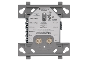
Uoxx S635 Control Unit Accessories Cp Notifier Ul Listed
Notifier ftm 1 wiring diagram. Set the address on the module per job drawings. Install module wiring in accordance with the job drawings and appropriate wiring diagrams. Ing in the same junction box as ftm 1. Notifier nfs manual online. Notifier nfse manual online. Page 5 wiring diagrams this page.
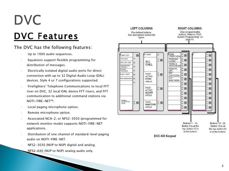
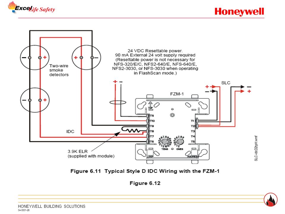
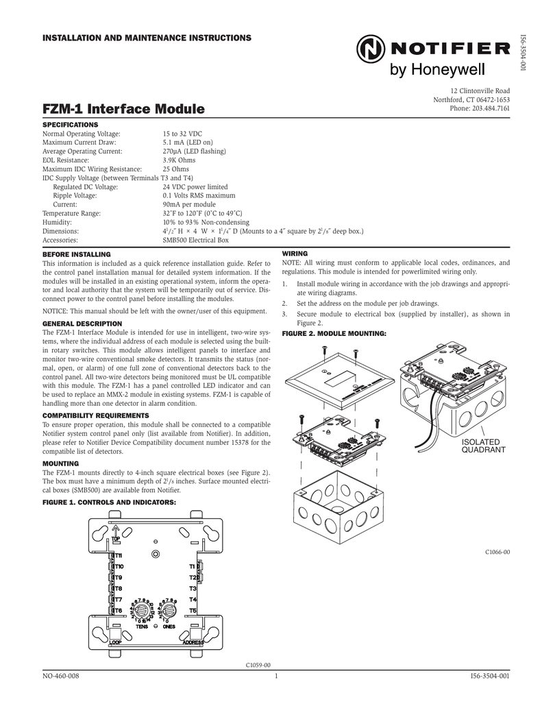
Any number of ul listed contact closure devices may be used. All wiring shown is supervised required. Surface mounted electrical boxes smb500 are avail able from notifier. Notifiers intelligent addressable firephone control module the ftm 1 provides the fire alarm control panel capability to monitor and control a circuit of up to two firefighter phones. Ftm 1 firephone control module installation and maintenance instructions 12 clintonville rd northford ct 06472 1653. Current rating maximum voltage load description application.
For installation instructions see the following documents. All wiring must conform to applicable local codes ordinances and regulations. Connect modules to listed compatible notifier control panels only. Connecting a releasing device to the fcm 1 rel. Ing power limited and non power limited wiring in the same junction box as fcm 1a. Fmm 1 connect modules to listed compatible notifier control panels only.
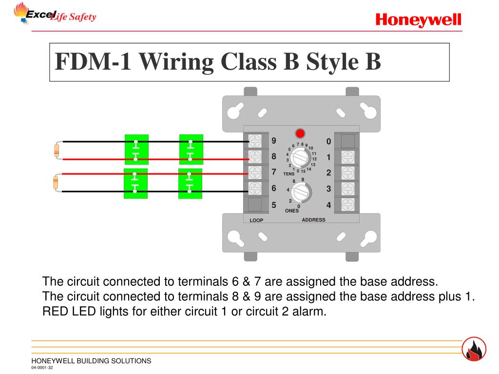
Set the address on the module per job drawings. A wiring diagram is a simplified conventional pictorial representation of an electric circuit. Ftm 1a firephone control. All wiring must conform to applicable local codes or dinances and regulations. Surface mounted electrical boxes smb500 are available. Fcm 1a installation document i56 1169.
Notifier fcm 1 wiring diagram. Releasing applications c limited energy cable cannot be used to wire a. Install contact closure devices per manufacturers installation instructions. This module is intend ed for power limited wiring only. This module is intended for power limited wiring only. The box must have a minimum depth of 218.
Variety of notifier fcm 1 wiring diagram. Trical boxes smb500 are available from notifier. It reveals the parts of the circuit as streamlined forms and the power as well as signal links in between the tools. All wiring shown is supervised and power limited. Install module wiring in accordance with the job draw ings and appropriate wiring diagrams. 9 8 7 6 54 3 2 1 0 10 2 3 4 56 789 0 678 5 4 3 2 1 9.
Compatible notifier system control panels only list available from notifier. Frm 1a installation document i56 3502. 16112018 16112018 3 comments on notifier fcm 1 wiring diagram. Mounting the fcm 1 mounts directly to 4 square electrical boxes see figure 2a. Connecting a releasing device to a fcm 1 module connecting an. Notifier slc wiring manual document 51253.
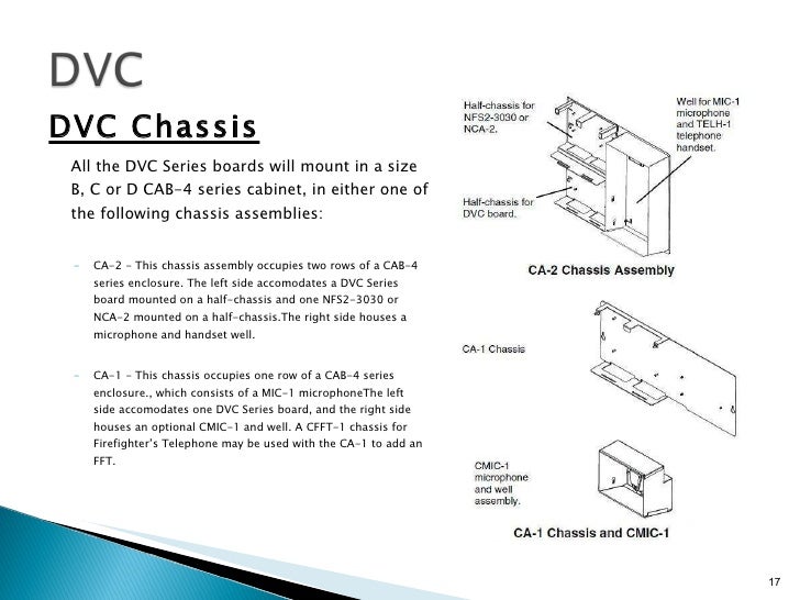
6724mt1wmf 6724mt2wmf mounting diagrams note cb500 module barrier which creates isolated quadrant. All wiring must conform to applicable local codes ordi. This module is used to connect a remote firefighter telephone to a centralized telephone console.
Gallery of Notifier Ftm 1 Wiring Diagram