Apr 4 2018 single phase forward reverse motor wiring diagram 1. July 28 2018 by larry a.

3 Phase Motor Diagram Diagram Base Website Motor Diagram
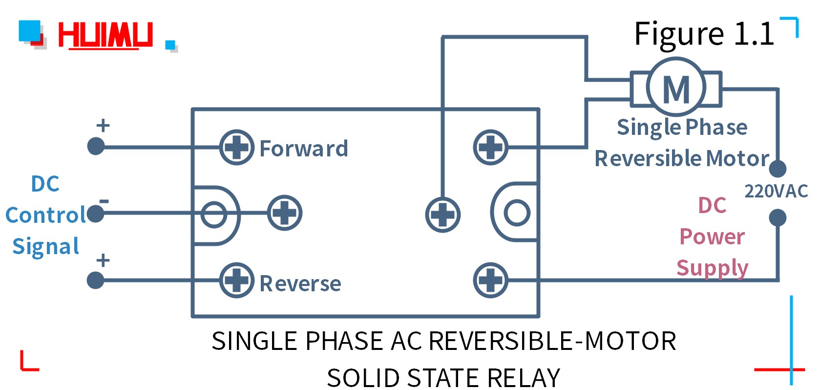
Single phase motor wiring diagram forward reverse. So as to be certain the electrical circuit is built properly single phase motor wiring diagram with capacitor is necessary. Single phase forward reverse motor wiring diagram concerbiz size. Learn how a capacitor start induction run motor is capable of producing twice as much torque of a split phase motor. As stated earlier the lines in a single phase motor wiring diagram forward reverse represents wires. In this example run winding lead t1 will always be connected to l1 and t4 will always be connected to l2. But for single phase ac motors the magnetic field only alternates back and forth.
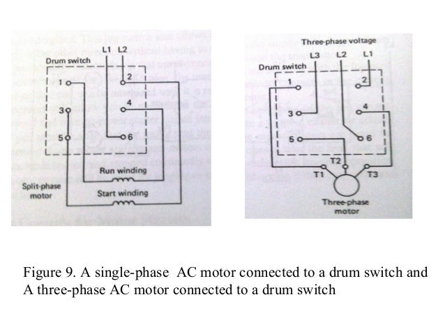
Each component ought to be placed and linked to different parts in particular manner. Three phase motor connection stardelta y δ reverse forward with regard to single phase forward reverse motor wiring diagram image size 621 x 686 px and to view image details please click the image. A schematic diagram of a forward reverse control for a single phase split phase motor is shown in figure 2913. But it doesnt imply link between the cables. A wiring diagram is a simplified conventional pictorial representation of an electrical circuit. Single phase motor reverse and forward connection.
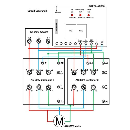
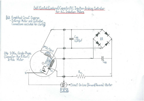
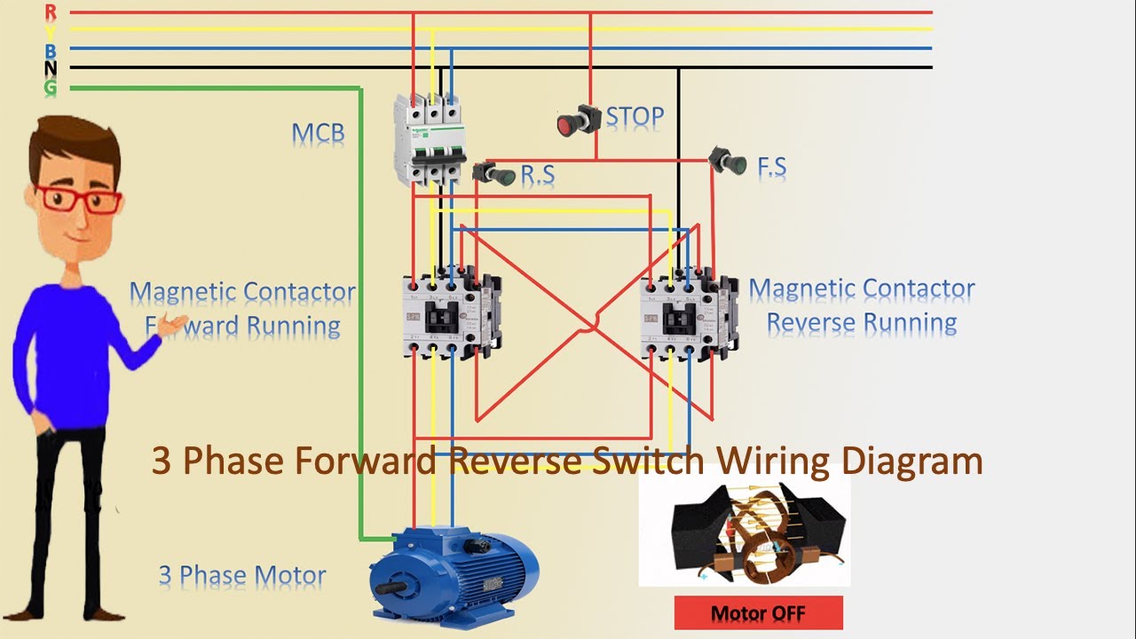
Some trickery is needed to create a rotating field. Reversing a split phase motor in this split phase motor the main winding label m is connected directly to 60 hz ac power while the other winding label o is wired in series with a capacitor c. Click here to view a capacitor start motor circuit diagram for starting a single phase motor. We use 2 magnetic contactors as forward reverse switch. Variety of single phase motor wiring diagram forward reverse. 800 x 600 px source.
At times the cables will cross. If not the arrangement wont work as it should be. Here is a picture gallery about single phase forward reverse motor wiring diagram complete with the description of the image please find the image you need. Wondering how a capacitor can be used to start a single phase motor. It reveals the components of the circuit as simplified forms as well as the power as well as signal links in between the tools. Once the starting winding has been determined use the motors wiring diagram to determine which starting winding leads to swap.
Here are a few of the leading drawings we obtain from various sources we wish these pictures will serve to you and with any luck very appropriate to just what you want about the reversing motor starter wiring diagram is. Notice that the control section is the same as that used for reversing three phase motors. A schematic diagram of a forward reverse control for a single phase split phase motor is shown in figure 2913. Injunction of 2 wires is generally indicated by black dot on the junction of 2 lines. Also read about the speed torque characteristics of these motors along with its different types.
Gallery of Single Phase Motor Wiring Diagram Forward Reverse