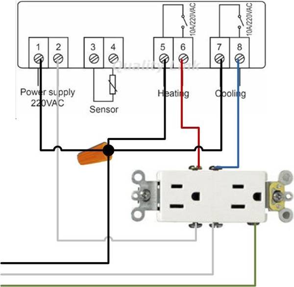
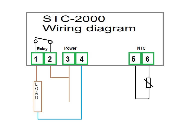
If you are using a 3 wire sensor then it connects to terminals 3 4 and 5. Wiring diagram 2 wires sensor 3 wires sensor thermocouple output relay output voltage power connection.

Oa 8131 Stc 1000 Wiring Diagram Furthermore Stc 1000 Wiring
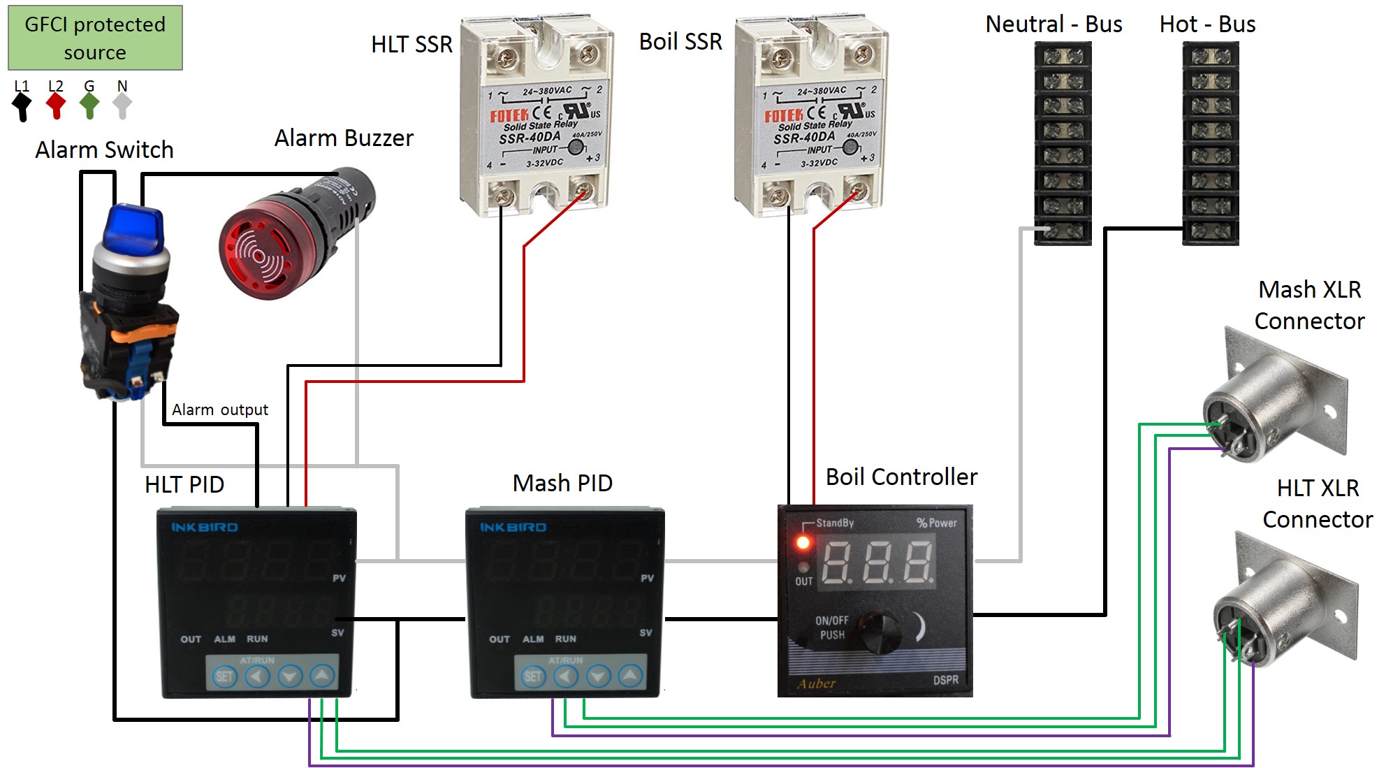
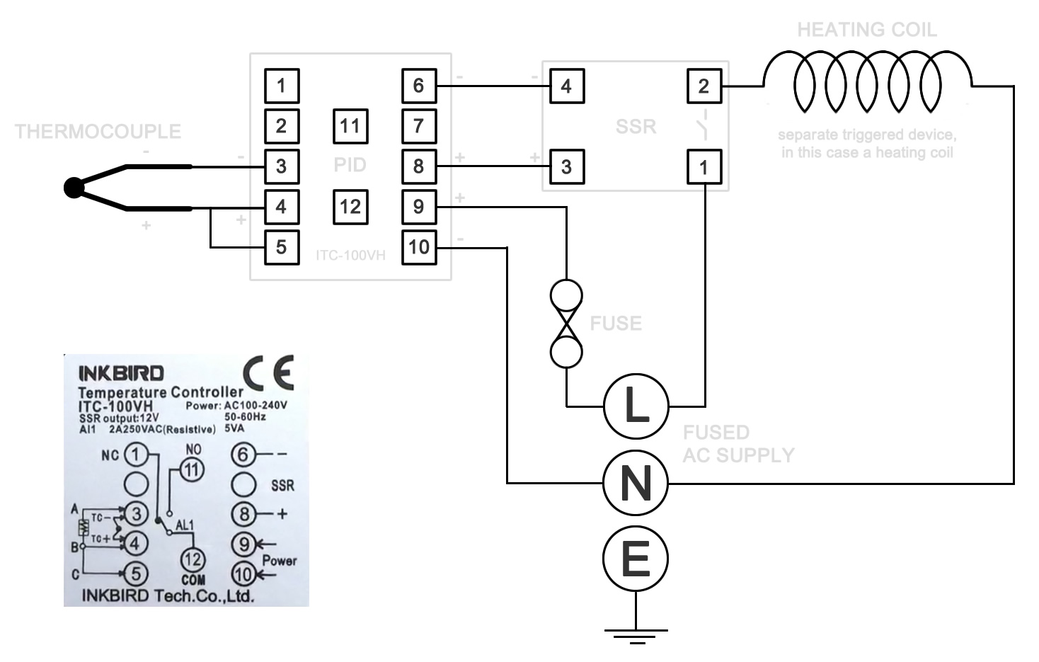
Inkbird wiring diagram. A pictorial diagram would reveal much more detail of the physical look whereas a wiring diagram makes use of a much more symbolic symbols to stress interconnections over physical look. There are many ways to wire these since they have many different function. In the instruction manual for your pid and possibly on a sticker on the case will be a wiring diagram like the one above. 9 and 10 terminals are for power connecting which its supply voltage should be match the item model. Inkbird is a company which dedicates its passion in producing and marketing of intelligent home automation products. How to wire a inkbird itc 1000 for use in a keezer bonus wiring diagram included.
Itc 1000f temperature controller manual thank you very much for selecting inkbird products. This video describes the inkbird itc 106vh pid and how to wire it for your system. This is the most basic method and will. View and download inkbird itc 100 user manual online. A wiring diagram is commonly made use of to troubleshoot troubles as well as making certain that all the connections have been made as well as that everything. Here you can download our latest user manuals drivers and other supporting materials from inkbird support department.
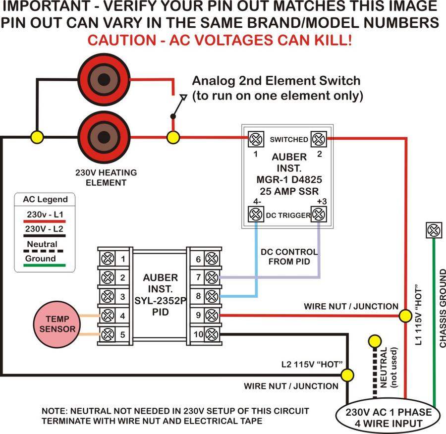
Pid wiring inkbird itc 100vh discount offer duration. Due to system maintenance problems the chart function in inkbird pro app is temporarily unavailable. Safety precautions ensure the product using within the specification. Lets start with the temperature sensor. Read the instruction manual carefully before use for right application and maintenance. Itc 100 controller pdf manual download.
Do not touch the terminals at least while power is being supplied. If you know how to translate it wiring everything up is quite simple.
Gallery of Inkbird Wiring Diagram