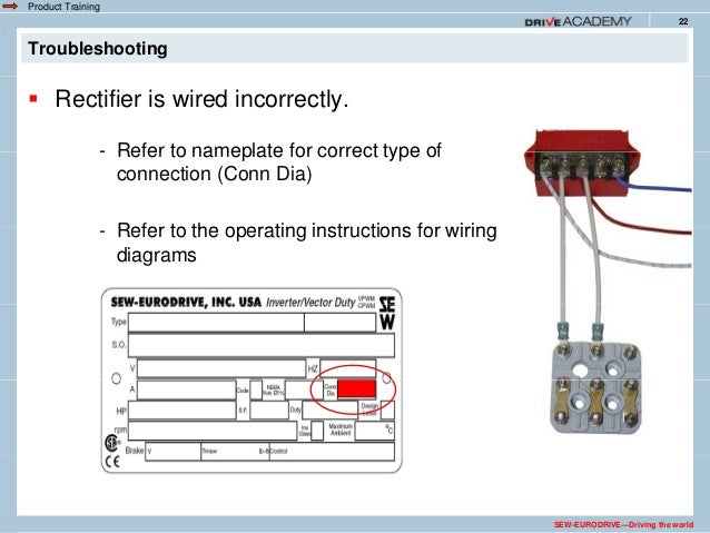
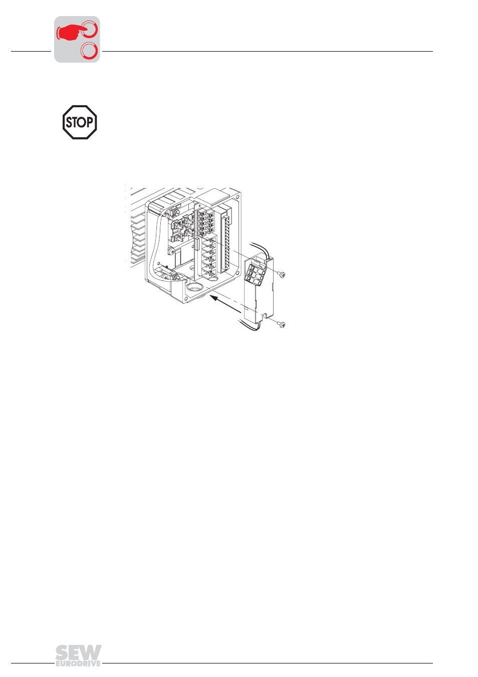
The brake releases automatically when power is applied to the motor. Pay attention to the wiring information and different data on the nameplate as well as observing the wiring diagram.
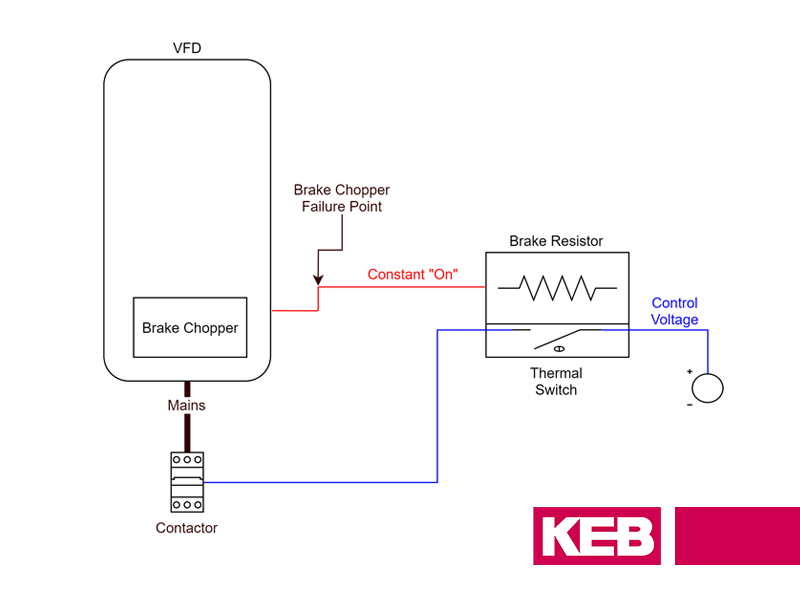
Replacing Clutch And Motor Brake Rectifiers With Keb
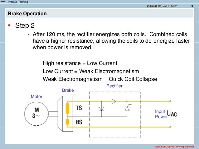
Sew eurodrive motor brake wiring diagram. A single speed motor the motor is started and run across the line and the brake voltage. Drive engineering practical implementation. It shows the components of the circuit as simplified shapes and the faculty and signal associates in the middle of the devices. Seweurodrive drives can be fitted with optional safety rated components such as brakes andor encoders. 2010 dr motor common connection diagrams 3. 14 2010 dr motor common connection.
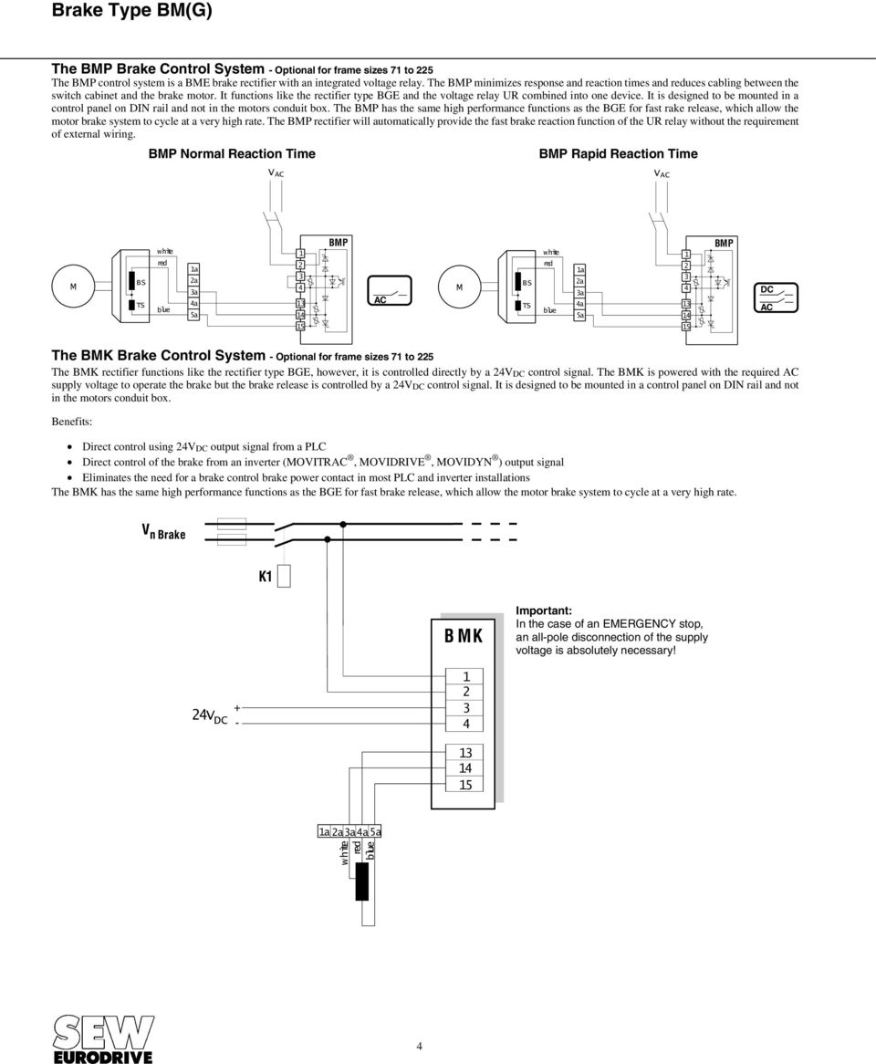
Back to top. Usa u5 v5 w5 l1 l2 l3 u2 v2 w2 t6 t1 t2 t3 t4 t5 u1 v1 w1 t7 t8 t9 u5 v5 w5 motor. It shows the parts of the circuit as simplified forms and the power as well as signal links in between the devices. Which allow the motor brake system to cycle at a very high rate. Assortment of sew eurodrive motors wiring diagram. The connection should be a continuous secure electrical connection no protruding wire ends.
This design is advantageous because it does not require a separate voltage supply and extra wiring for the brake. Wiring diagrams brake rectifiers and coil data. The bme can we wired to operate for. The brake can be wired to the motor terminal block under the following conditions. A wiring diagram is a simplified standard pictorial representation of an electrical circuit. Sew eurodrive motor wiring diagram wiring diagram is a simplified pleasing pictorial representation of an electrical circuit.
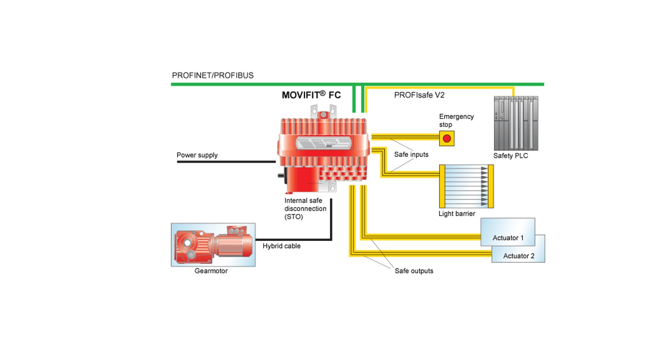
Use the cable end equipment intended for this purpose. Requiring no additional brake supply wiring. In many wiring diagrams the brake voltage is tapped directly from the motors terminal block. Observe nameplate data and the wiring diagram in the terminal box. The bmk brake control system optional for frame sizes 71 to 225. An integrated safety rated brake is clearly labeled by the fs logo eg.
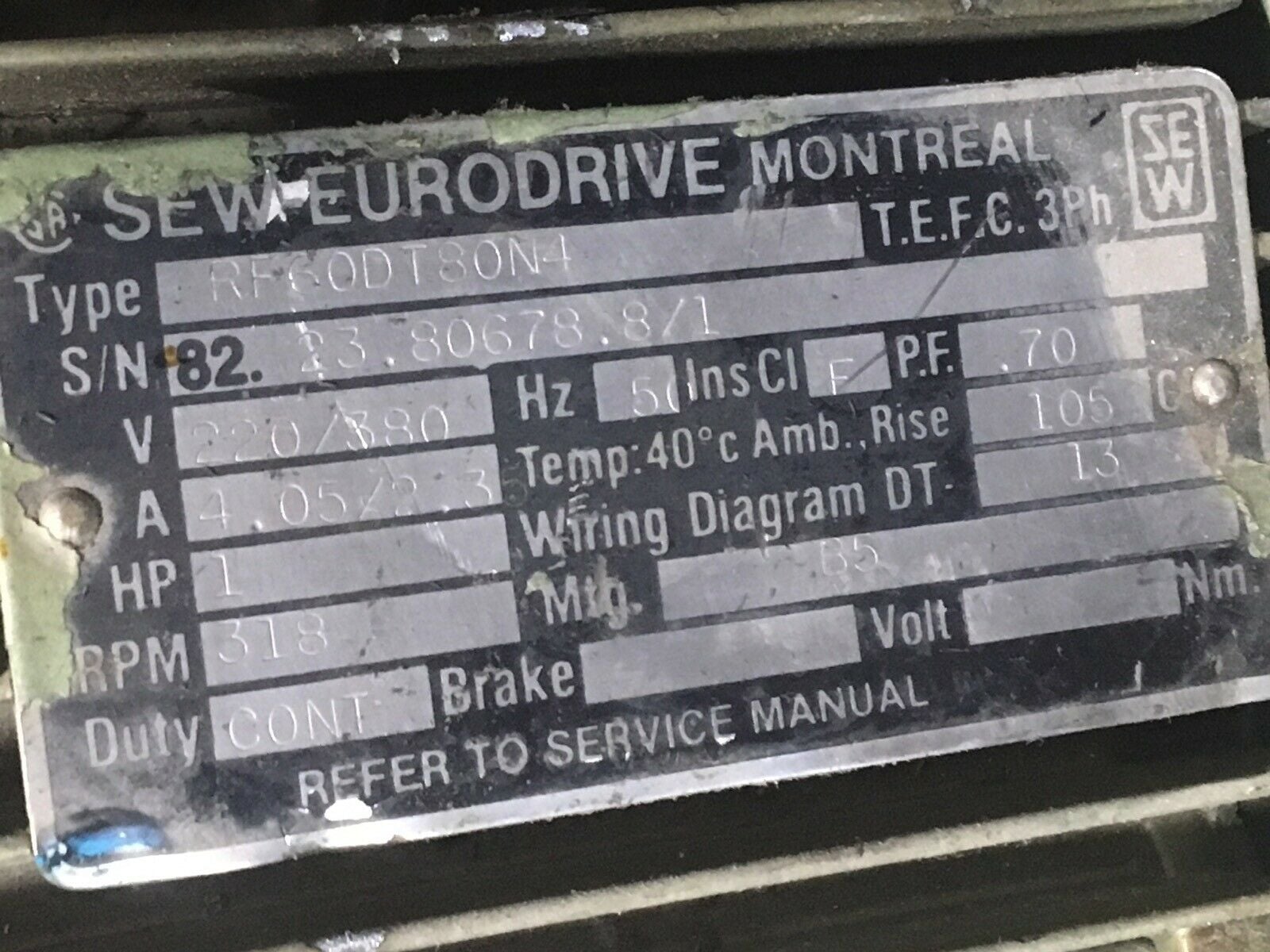
Ac motors brake motors drdvdtdtedve asynchronous servomotors ctcv. Gear units r7 f7 k7 s7 series spiroplan w operating instructions cm synchronous servomotors. Connection diagram dt79 example motor voltages. Ac motors dr71 225 315 operating instructions. 230yy460y volts 60 hz 200yy400y volts 50 hz. Usa t12 t13 single speed dual voltage low voltage see motor nameplate high voltage see motor nameplate connection dt79 diagram l1 l2 l3 u2 v2 w2 t6 t1 t2 t3 t4 t5 u1 v1 w1 t7 t8 t9 10939p000004 sew eurodrive inc.
Fs02 on the motor nameplate.
Gallery of Sew Eurodrive Motor Brake Wiring Diagram