Here is a picture gallery about 20 wiring diagram complete with the description of the image please find the image you need. Paragon defrost timer 8145 20 wiring diagram paragon defrost timer wiring furthermore paragon defrost timer 8145 rh beinclover co.

Supco Refrigeration Catalog Pipe Fluid Conveyance Hvac
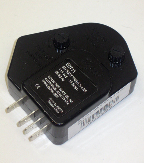
Edt11 defrost timer wiring diagram. Edt11 electronic defrost timer 120v 15a. Test the defrost timer. Paragon sell sheet shows model numbers and wirings diagrams replace with tt or ct series. Walk in freezer defrost timer wiring diagram wiring diagram is a simplified suitable pictorial representation of an electrical circuitit shows the components of the circuit as simplified shapes and the skill and signal associates together with the devices. Wh4 four wire adapter harness kit if needed. When the defrost timer is in defrost mode you should measure an open circuit between pin 1 main power input and pin 4.
1 and lead 4 to no. The new energy efficient edt. Once the 10 hours is over the defrost timer will switch back to pin 2 activating the defrost. The paragon series auto voltage defrost timer is designed competitive voltage specific mechanical defrost timers eliminating wiring diagrams. Edt11 defrost timer universal electr onic 34 hp. Allied refrigeration 440 823 5720 cleveland ohio.
You can test a defrost timer by measuring the resistance in the circuits when the timer is in each mode. In these applications use the supco no. 3 of the original wiring lead 2 to no. The edt series defrost timers utilize adjustable timing and industry standard wiring to replace most domestic and many commercial defrost timers. 4 lead 3 to no. 115 vac 34 hp 20 amp defrost timer the edt series defrost timers utilize adjustable timing and industry standard wiring to replace most domestic and many commercial defrost timers.
Wire harness lead 1 to no. Original wire no 5 will not be used it should be sleeved or taped and. The paragon defrost and the tork electric timers offer versatility and. Electronic adjustable defrost timers were designed and developed by supco engineers. I remove a bad grasslin time clock and replace it with a paragon time clock. 32f to 135f 0c to 57c.
Paragon defrost timer wiring diagram paragon defrost timer wiring regarding 20 wiring diagram image size x px and to view image details please click the image. In this video you can learn about the defrost timer wiring diagram of a frost free refrigerator and circuit diagram step by step details about the function of the timer bimetal heater thermostat.
Gallery of Edt11 Defrost Timer Wiring Diagram