In reverse osmosis an applied pressure is used to overcome osmotic pressure a colligative property that is driven by chemical potential differences of the solvent a thermodynamic parameter. Water solvent can cross the membrane.
32 5 Stage Ro System Diagram Wiring Diagram List
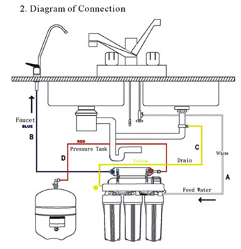
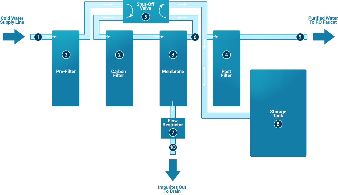
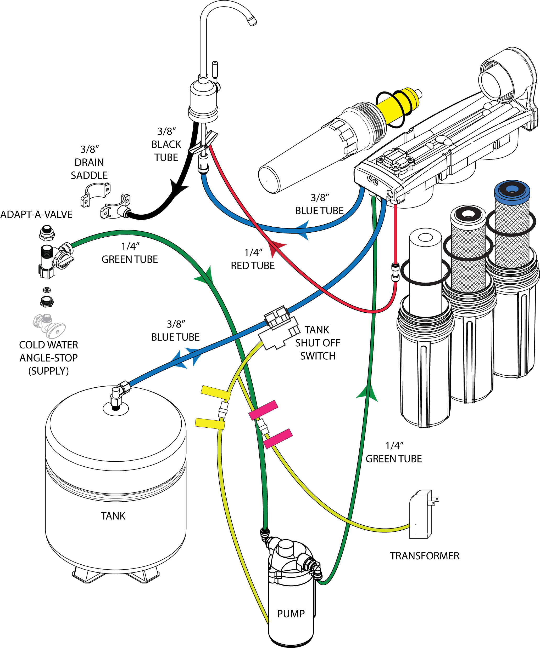
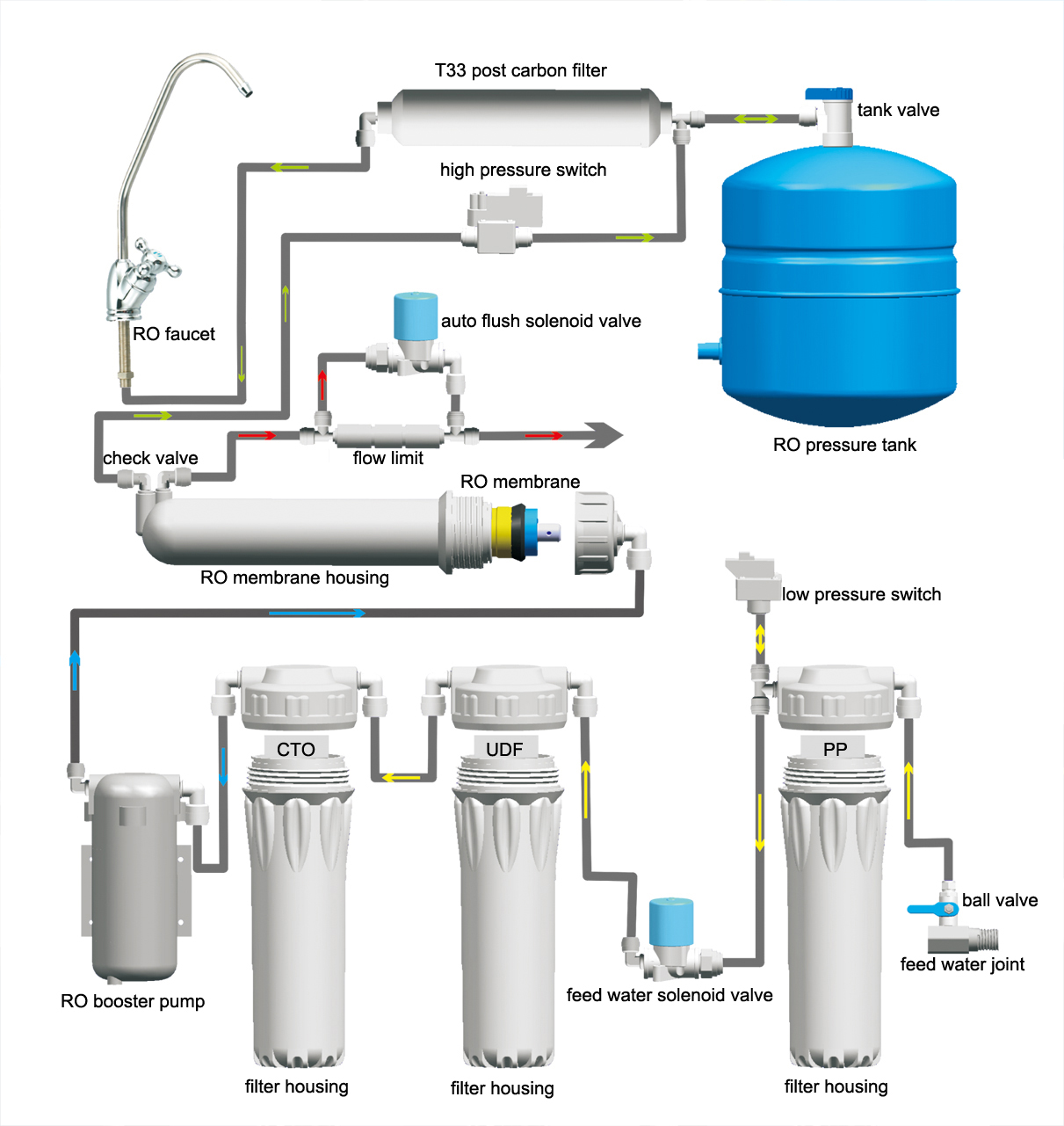
Reverse osmosis wiring diagram. Flow diagram for 5 stage reverse osmosis water systems note. 1 raw water tank 2 feedback wash pump 3 prechlorination 4 automatic multimedia filter 5 dechlorination 6 antiscalant 7 reverse osmosis system 8 post ph 9 post chlorination 10 product water tank. A bracket is provided so they can be mounted under the sink or in a basement. Flow diagram for 5 stage reverse osmosis water systems note. Angle stop valve the angle stop valve connects to the cold water line to supply water to the ro system and provides an easy ability to shut off the water supply when servicing the unit. Ro module the ro module is the main component and holds the pre filters membrane and post filter.
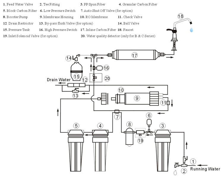
Under the sink reverse osmosis water systems model. The arrow is pointing to the direction of water flow. Reverse osmosis ro is a water purification process that uses a partially permeable membrane to remove ions unwanted molecules and larger particles from drinking water. The pump has inlet and outlet please look for the arrow on the pump head. 2 product specification. Reverse osmosis system components.
Ro 585 5 stage ro system 85 galday at 80 psi. Routine maintenance is essential to the longevity. There is additional information about installation of a ro system on this web site. By carefully reading this instruction manual and following the operational guidelines you will insure a successful installation and reliable operation. Reverse osmosis or ro is a filtration method that is used to remove ions and molecules from a solution by applying pressure to the solution on one side of a semipermeable or selective membrane. The auto shut off valve uses the back pressure amount created by the float valve.
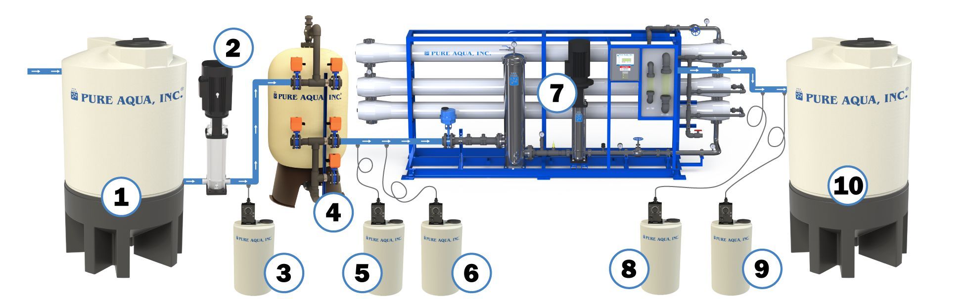
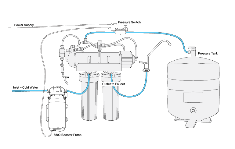
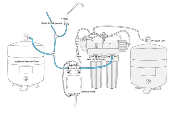
On the any page hover over the words installation. Diagram 5stage rouv this is a diagram of a 5 stage reverse osmosis system with uv light. Click on the link diagram 5 stage rouvand you will be transferred to the diagram. The pressure switch tso does not have inletoutlet connect to either end. The solenoid valve eso has inlet and outlet also note. Industrial reverse osmosis ro systems diagram engineered in usa by pure aqua inc.
Large molecules solute cant cross the membrane so they remain on one side. The purevalue reverse osmosis drinking water system has been designed for quick and simple installation and maintenance. Ro 585a 5 stage ro system with digital water quality tds meter ro6100dint 6 stage rodi system 100gpd single o utput ro6100di 6 stage rodi system 100gpd dual outputtankfaucet. Automatic shut off valve aso diagram for reverse osmosis system shuts off waste water from exiting the ro system for a video on how to install this valve go to.
Gallery of Reverse Osmosis Wiring Diagram