When illuminated it indicates the relay coil is energized. A red led is provided on both models.

6c232e1 Fire Alarm Pam Relay Wiring Diagram Circuit Wiring
Pam relay wiring diagram. The relay may be energized by one of three input voltages. The pam 4 relay provides 100 amp form c contacts and may be energized by a wide voltage range from 9 vdc to 40 vdc. A red led is provided which when illuminated indicates the relay coil is energized. Fire alarm pam relay wiring diagram circuitt wiring library pdf mde 2713a universal distribution box installation manual pdf tp39167202 2010 c30 s40 v50 c70 supplement wiring diagram pdf. Thus they can be wired to switch any other power load or low voltage load see. The pam 1 may be mounted by using the double sided adhesive.
The pam 4 relay provides 100 amp form c contacts and may be energized by a wide voltage range from 9 vdc to 40 vdc. The pam 1 relay is an encapulated 24vdc multi voltage device providing 100 amp form c contacts. The pam 1 relay is encapsulated multi voltage device providing 10 amp form c contacts. 24 vac 24 vdc or 115 vac. The pam 2 relay pro vides 70 amp form c contacts and may be energized by. Wiring diagrams pam 1 pam 2 pam 4.
Pam 1 the pam 1 relay is an encapsulated multi voltage device providing 10 amp form c contacts. A red led is provided on both models. The relay may be energized by one of three input voltages. A red led is provided which when illuminated indicates the relay coil is energized. Wiring diagrams pam 1 pam 2 pam 4. The pam 1 relay provides 100 amp form c contacts and may be energized by one of three input volt ages.
The relay may be energized by one of three input voltages. If you need a relay diagram that is not included in the 76 relay wiring diagrams shown below please search our forums or post a request for a new relay diagram in our relay forum. 24v ac 24v dc or 115v ac. The pam 1 may be mounted by using the double sided adhesive. The pam 1 may be mounted by using the double sided adhesive tape the. 24 vac 24 vdc or 115 vac.
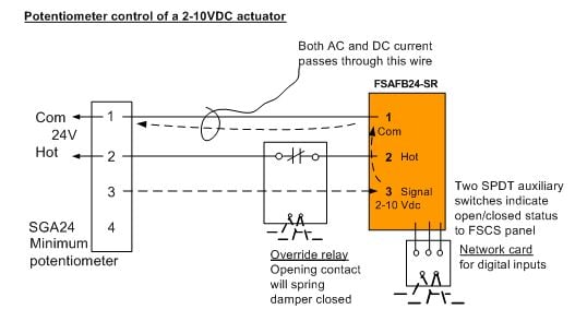
Air products controls inc. A red led is provided which when illuminated indicates the relay coil is energized. Dozens of the most popular 12v relay wiring diagrams created for our site and members all in one place. The relay contacts are isolated from the input power and the dry contact input. The power to energize the relay can be brought to the relay on a separate pair of wires along with the control output of the controller or can be a local power source near the relay. 24 vac 24 vdc or 115 vac.
When illuminated it indicates the relay coil is energized. Pam 1 encapsulated relay single spdt 100 a form c contact pam 2 encapsulated relay single spdt 70 a form c contact pam 3 end of line relay 30 a form a contact pam 4 encapsulated relay single spdt 100 a form c contact wiring diagrams specifi cations model number pam 1 pam 2 pam 3 pam 4. Pam 1 pam 2 and pam 4 multi voltage relay modules are encapsulated multi volt age devices.
Gallery of Pam Relay Wiring Diagram