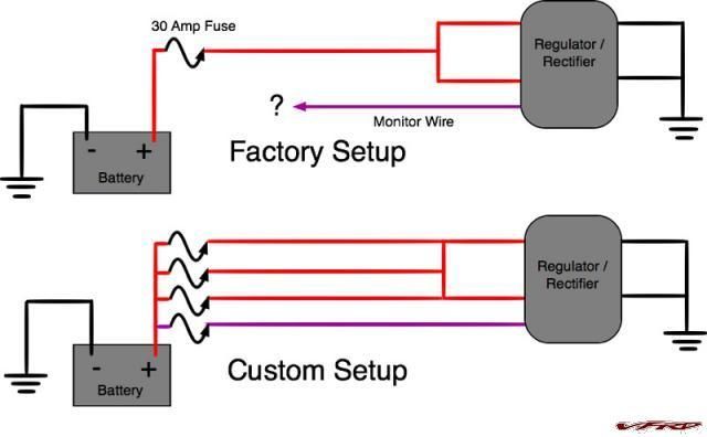
Regulator rectifier diagram here you are at our site this is images about regulator rectifier diagram posted by maria nieto in wiring category on may 08 2019. Many ricks motorsport electrics rectifierregulators eliminate what is commonly referred to as a signal wire on oe pieces.

Wingsmoto Rectifier Regulator 4 Wires Voltage Atv Gy6 50
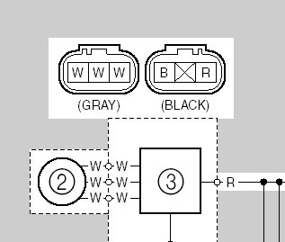
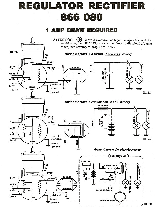
Regulator rectifier wiring diagram. How to wire the 5 cables not in a row. Regulatorrectifier 7003 rr150 2 yellow wires. Regulatorrectifier wiring guide 010 elv 116 tech support. If not the structure will not work as it should be. 17022019 17022019 7 comments on briggs and stratton voltage regulator wiring diagram shunt is designed to read voltage drops due to the resistance of the metal be tween the two wires of the same color feeding a regulatorrectifier is a rectified. Use a 1 phillips adjust voltage dial.
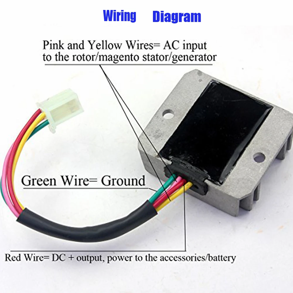
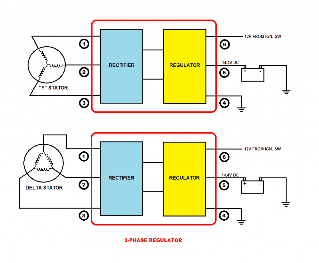
Connect to negative battery terminal. Wiring diagram for voltage regulator. 2 yellow wires ac inputs whitered dc output blackyellow dc output and a brown wire. Each component ought to be set and linked to different parts in particular manner. For more information on what phase means check out our regulator rectifier technical guide how do regulator rectifiers work. 2 phase regulator rectifier wiring diagram links.
How to make a reliable motorcycle voltage regulator. Pitbike rectifierregulator wiring diagram isaac p. Mercury outboard rectifier wiring diagram mercury outboard rectifier wiring diagram every electric structure is made up of various unique pieces. Connect to lighting leads from stator. Trail tech stators have yellow lighting leads. Weve categorized all our regulator rectifier wiring diagrams into 2 phase and 3 phase systems.
Remove blue paint from adjustment dial marked voltage fig. We know the 3 yellow are aligned suzuki 1984 gsx 1100 e question. The blue wire functions as a charge limiter. The yellows all come from the alternator you can connect these in any order to each other the red wire from the rectifier can be connected directly to the battery and the black is the earth wire. Connect to positive battery terminal and to positive wires of all accessories on the lighting circuit. For example on a 1981 kawasaki kz440 there are 5 wires going to the oe part.
4 pin regulator rectifier wiring diagram. This is the ultimate guide to the humble motorcycle regulator rectifier.
Gallery of Regulator Rectifier Wiring Diagram