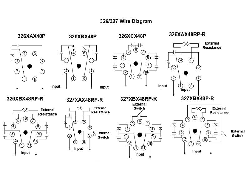
Assortment of timer relay wiring diagram. Assortment of time delay relay wiring diagram.
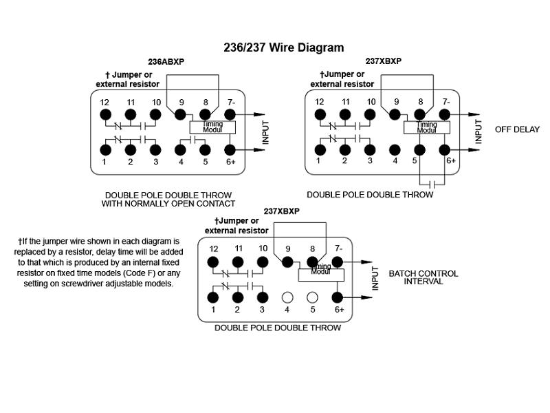
236 237 Series Nuclear Grade Time Delay Relay
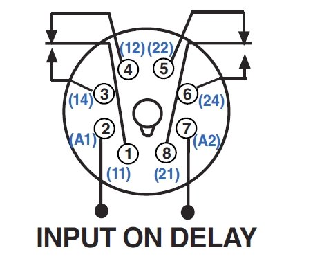
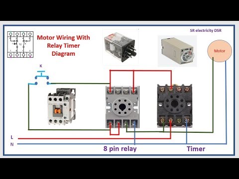
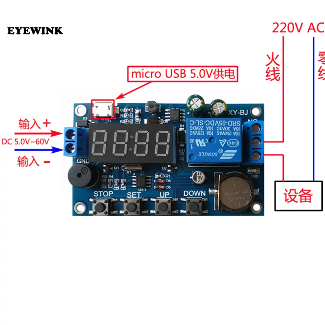
Timer relay wiring diagram. In the below wiring diagram i shown also the star delta ic timer wiring diagram. Input voltage must be removed to reset the time delay relay de energize the output. It shows the components of the circuit as simplified shapes and also the power as well as signal connections in between the gadgets. A wiring diagram is a streamlined traditional photographic representation of an electrical circuit. Each component should be placed and linked to other parts in particular manner. The timer function 1 is on delay it allows to supply power after a period of time t.
3 simple ways to build an adjustable timer circuit diagram 1 to 10 minute timer cyclic on off timer and arduino timer to adjust long intervals of time. Voltage the time relay t upon application of input begins. On delay timer circuit diagram wiring diagram contactor with push button circuit diagram of delay timer on off power off delay timer circuit diagram 2 way lighting circuit triggering transformer push button fan switch light activated switch circuit diagram wd081 text. And 8 pin finder relay wiring diagram. At the end of the time delay t the output is energized. In the below staircase timer wiring diagram i shown 2 8 pin relay socket a on daily timer a 8 pin finder type relay 2 push button switches a light bulb and wiring connection.
A wiring diagram is a streamlined conventional photographic depiction of an electric circuit. It reveals the elements of the circuit as simplified shapes as well as the power and also signal links between the gadgets.
Gallery of Timer Relay Wiring Diagram