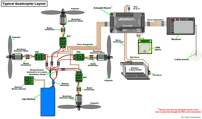
It shows the components of the circuit as simplified shapes and the aptitude and signal connections along with the devices. This was the beginning of a story of a very successful open source project outperforming individual corporate development.
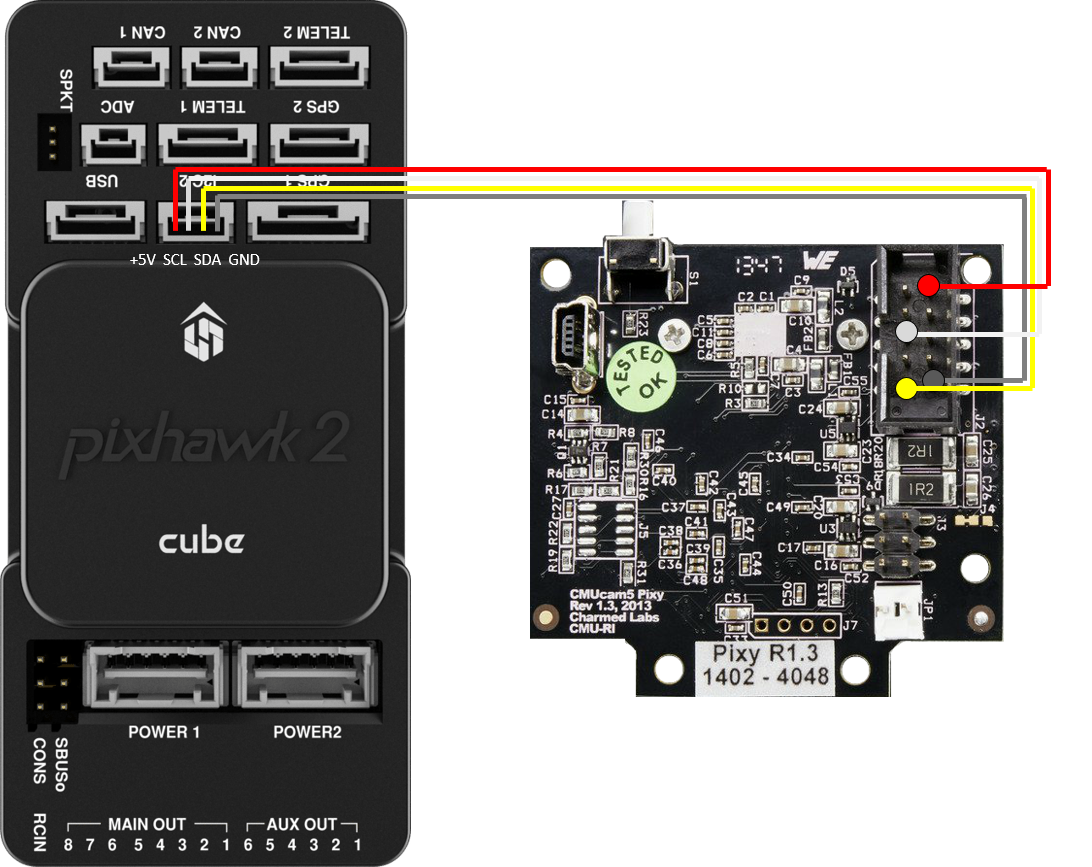
4a Pixhawk Connection Irlock
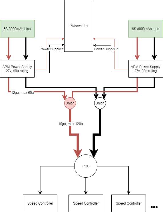
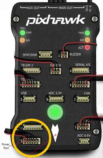
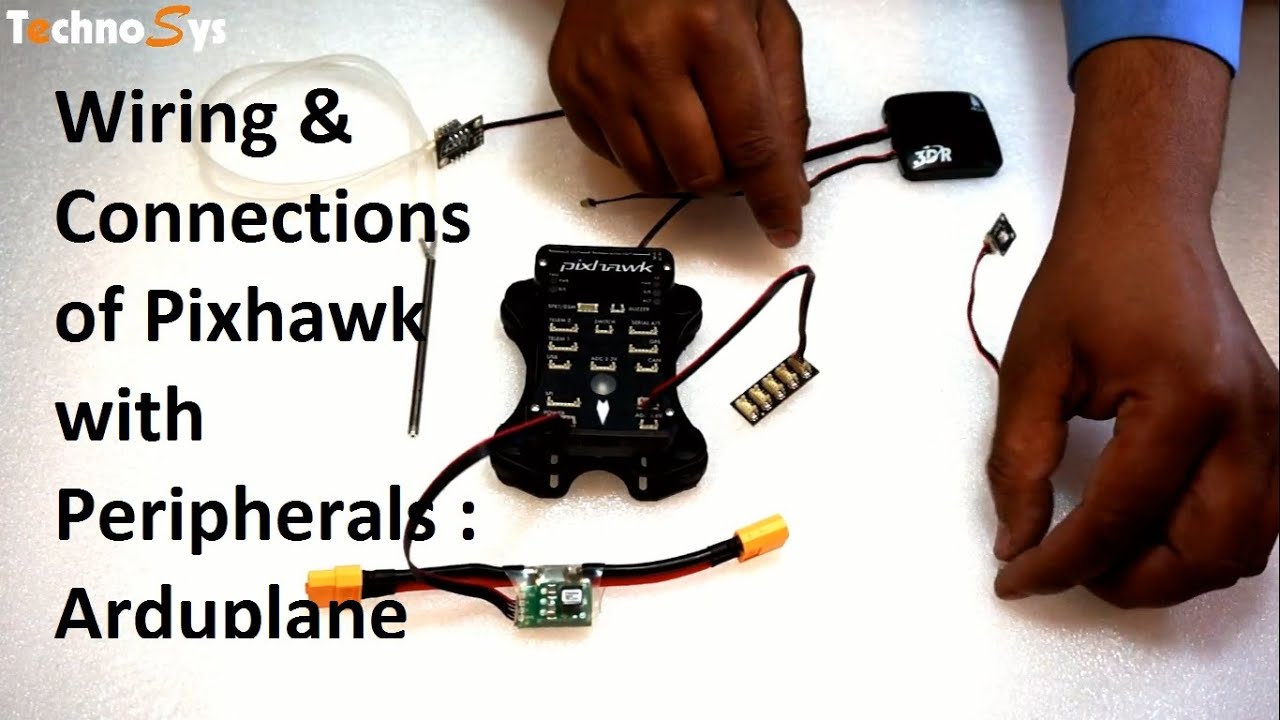
Pixhawk 2 wiring diagram. The 3dr pixhawk is no longer available from 3dr. Pixhawk wiring quick start. The cube flight controller previously known as pixhawk is a flexible providing consistent autopilot and manual override mixing modes fixed wing use. Other flight controllers based on the pixhawk fmuv2 architecture are available from other companies these share the same connections outputs functions etc. This quick start guide shows how to power the 3dr pixhawk flight controller and connect its most important peripherals. The power port simultaneously powers pixhawk and reads voltage and current analog measurements produced by an optional power module.
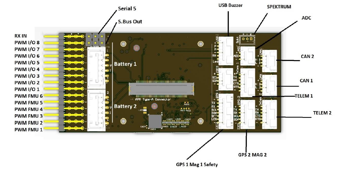
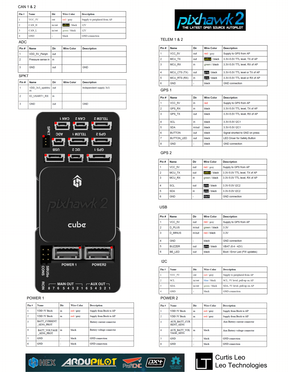
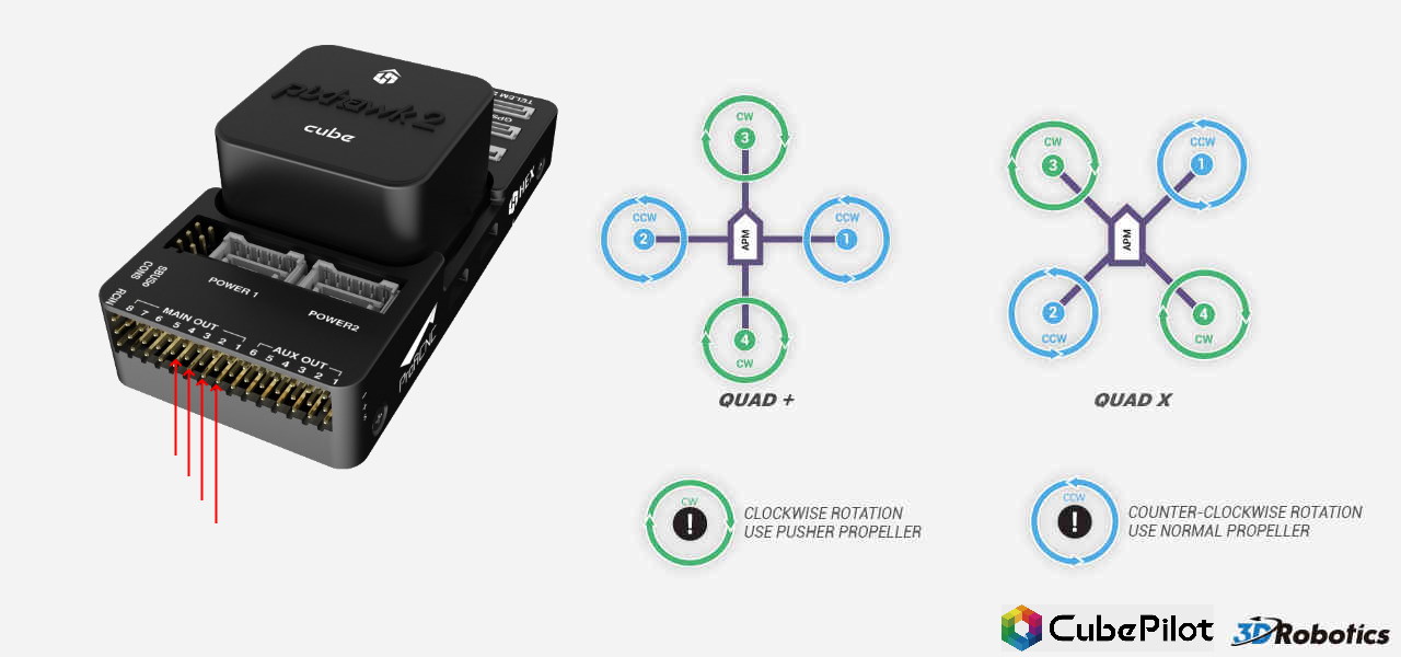
Power pixhawk pixhawk is typically powered via its power port as shown in the picture below. The cube flight controller previously known as pixhawk 21 is a flexible autopilot intended primarily for manufacturers of commercial systems. Information about powering the pixhawk can be found in the topic powering the pixhawk. Each part should be placed and connected with different parts in particular manner. Pin 1 motor 1 pin 5 motor 5 pin 2 motor 2 pin 6 motor 6 pin 3 motor 3 pin 7 motor 7 pin 4 motor 4 pin 8 motor 8 for planes for planes connect the control channel wires to the main output signal pins. Pin 1 aileron pin 2 elevator pin 3 throttle pin 4 rudder.
And are wired in a similar way. Otherwise the structure will not work as it should be. Pixhawk wiring diagram pixhawk 2 cube wiring diagram pixhawk 2 wiring diagram pixhawk 248 wiring diagram every electrical structure is composed of various diverse components. Pixhawk wiring diagram pixhawk 2 cube wiring diagram pixhawk 2 wiring diagram pixhawk 248 wiring diagram every electrical structure is composed of various diverse components. For traditional single wire per channel pwm receivers a ppm encoder can be used to convert the receiver outputs to ppm sum. Connect one wire for each motor to the corresponding pin.
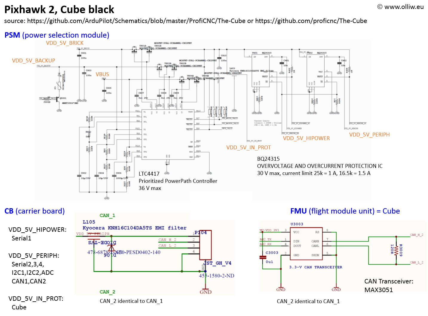
Pixhawk wiring quick start. Otherwise the structure will not work. Pixhawk 2 wiring diagram wiring diagram is a simplified pleasing pictorial representation of an electrical circuit. It is based on the pixhawk project fmuv3 open hardware design and runs px4 on the nuttx os. Each part should be placed and connected with different parts in particular manner. Multiplex srxl version 1 and version 2 receivers.
During this time the team created mavlink pixhawk px4 and qgroundcontrol which are todays most used standards for flight control hardware and autopilot software in the drone industry. Pixhawk 21 wiring diagram pixhawk is the latest iteration of pixhawk which is an independent open hardware signals wires to the rc pins using the provided 3 wire servo cable. The controller is designed to be used with a domain specific carrier board in order to reduce the wiring improve reliability and.
Gallery of Pixhawk 2 Wiring Diagram