Timing diagram 0 v load voltage 0 v input voltage transfer load energized time delay time time 1. Icm controls icm102 icm102 delay on make timer 03 10 minute adjustable delay mode of operation when power is applied to the input the time delay begins.
Installation
Icm102 wiring diagram. D see arrow below. Helps to reduce power surges. Select the desired time delay. For 24 vac circuits apply control as packaged. Some functions noted by an asterisk in the tables at right require the use of a trigger to initiate the unit as indicated by the dotted line in the wiring diagrams above. Select the desired time delay.
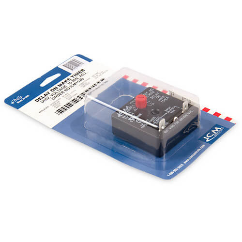
Universal voltage operation higher 15 amp power rating knob adjustable time delays works with anticipator type thermostats one model replaces many in field. Icm102 time delay relays delay on make dom share product delay on make timer with 03 10 minute adjustable delay universal 18 240 vac details. Connect terminals in series with the starting device as shown in the wiring diagram below. For 120240 vac circuits cut the jumper wire. Timing diagram 0 v load voltage 0 v input voltage transfer load energized time delay time time 1. For 24 vac circuits apply control as packaged.
Please note that due to corona covid 19 virus some orders may be delayed in delivery by upsusps customer service call 402 678 2765 8 am to 5 pm cst thank you. For triggered dc input voltages make sure the polarity matches the connection diagram. Connect terminals in series with the starting device as shown in the wiring diagram below. We are still shipping orders daily. For 120240 vac circuits cut the jumper wire. After the time delay is complete the load energizesbrbr delay on make timers are ideal for compressor staging and stagger starting multiple motors and other equipment.
Wire to input voltage as shown in fig.
Gallery of Icm102 Wiring Diagram