Pid controller enable 6. Wellborn collection of pid temperature controller wiring diagram.
Precise Digital Temperature Controller Circuit Working And
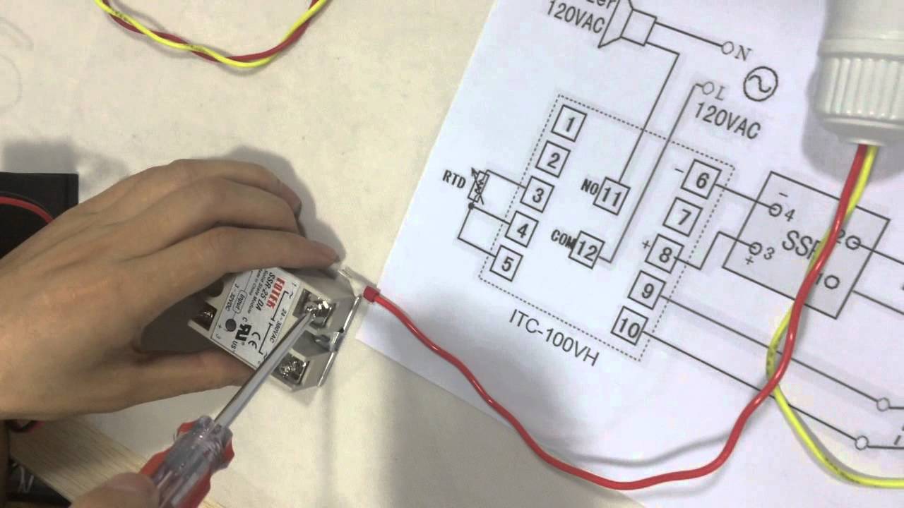
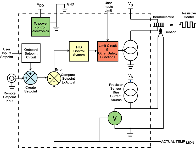
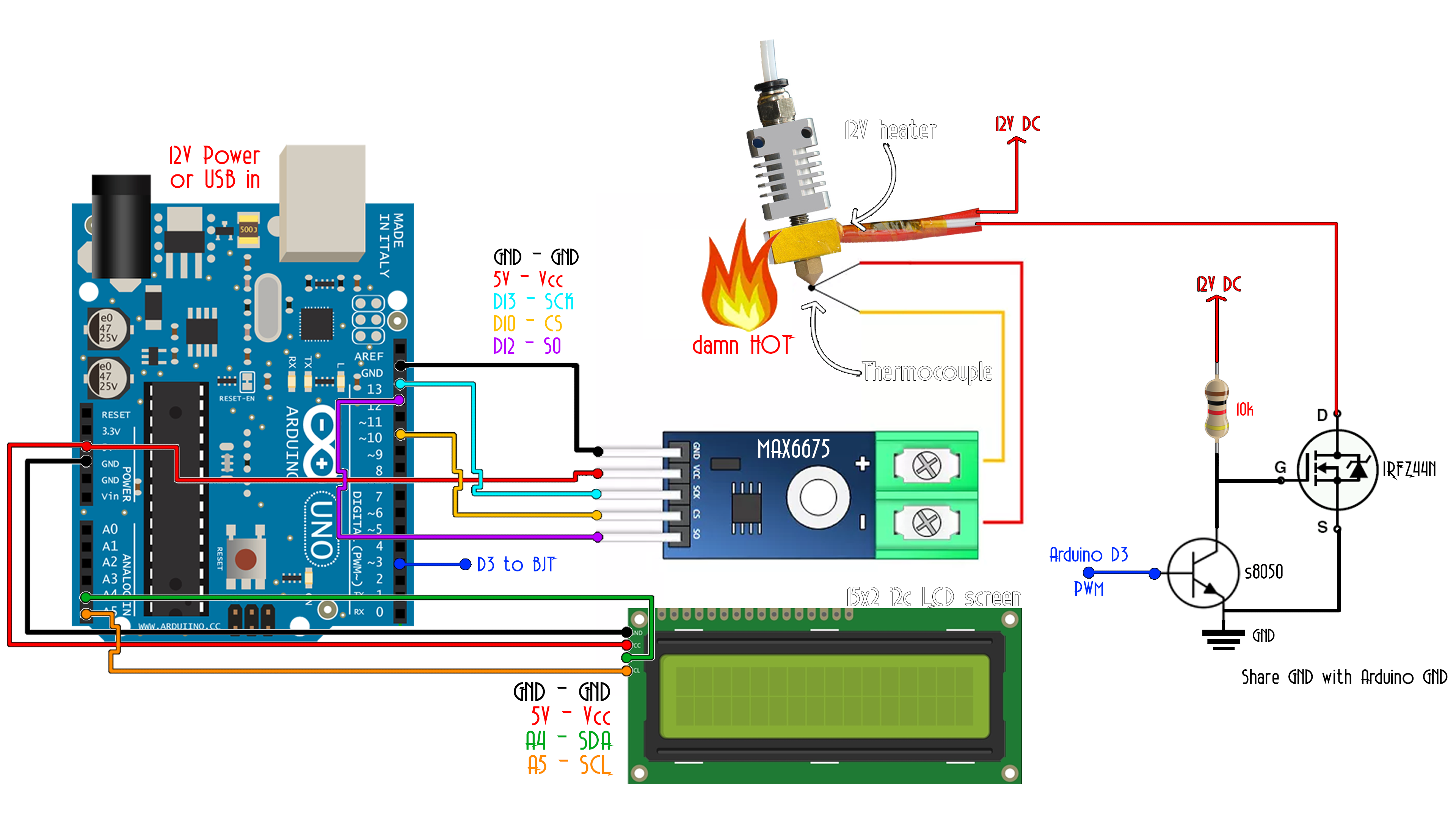
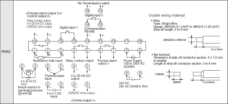
Pid temperature controller wiring diagram. It reveals the components of the circuit as streamlined shapes and the power and also signal connections in between the devices. It reveals the elements of the circuit as streamlined forms and also the power and also signal links between the tools. April 25 2020 by larry a. In position eha pid 201 a 20 inpos test points behind front panel dil switches mode front view general description this product is one of a range of snap on control modules for mounting into control cabinets using rails to din en 50022 or din en 50035. How to wire the inkbird itc100vh pid with a pt100 thermocouple ideal accurate temperature control solution for powder coating ovens when curing powder coating work it is beneficial to have an. A wiring diagram is a simplified standard photographic representation of an electric circuit.
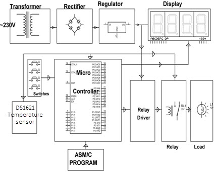
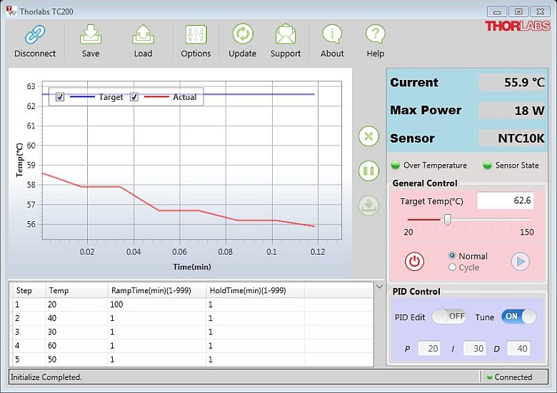
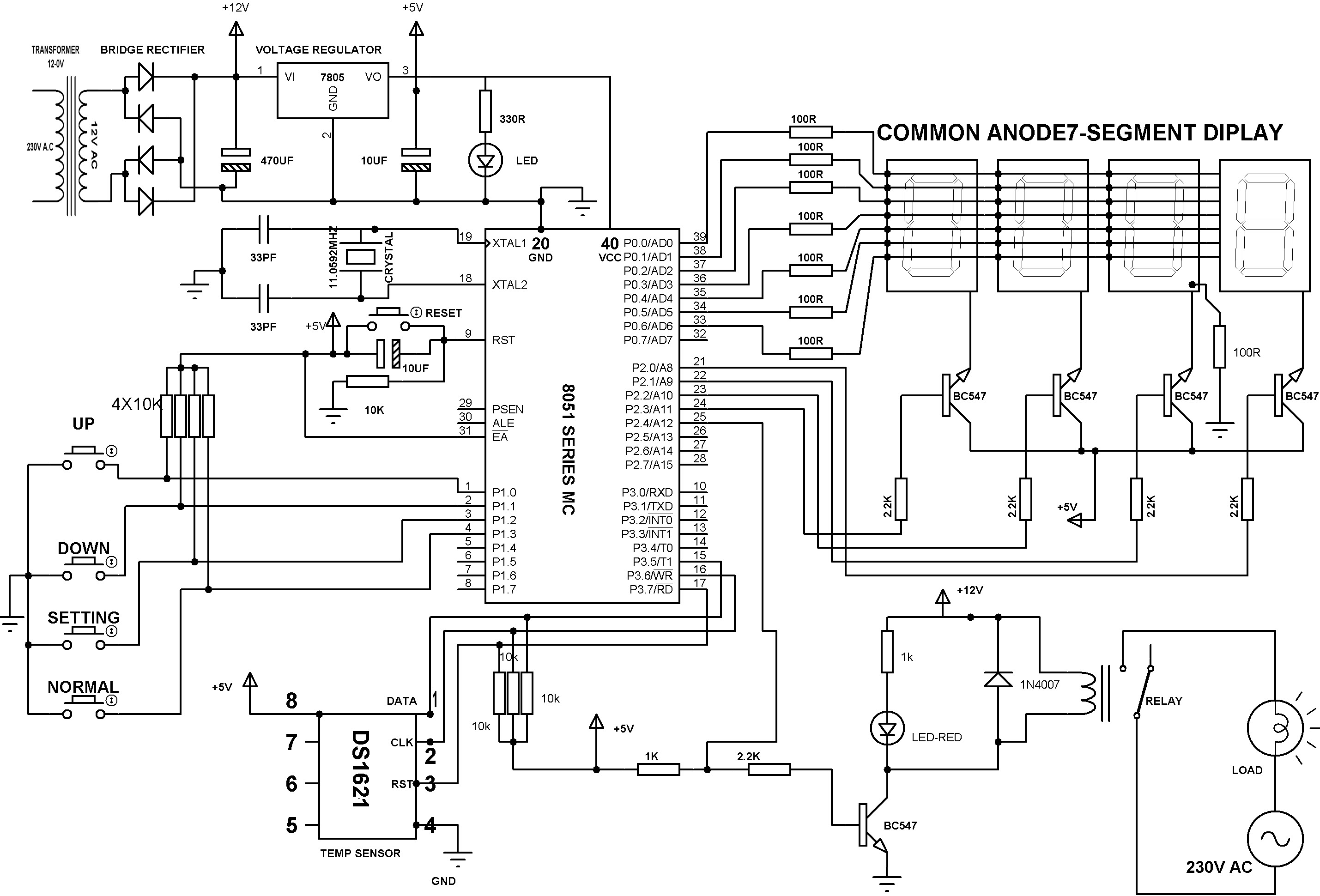
Digital temperature controller circuit and working fig. The module is ideally suited for use with. 2 shows circuit diagram of the digital temperature controller. 1 for thermocouple tctc 6 7 8 910 thermocouple. Basic pid temperature controllertc518. Operating instructions tc518 48 x 48 specifications sensor factory set.
The circuit is built around microcontroller pic16f877a ic1 precision thermocouple amplifier ad8495 ic2 k type thermocouple connected at con3 162 lcd lcd1 single changeover relay rl1 and a few common components. Collection of temperature controller wiring diagram. A wiring diagram is a simplified traditional pictorial representation of an electrical circuit.
Gallery of Pid Temperature Controller Wiring Diagram