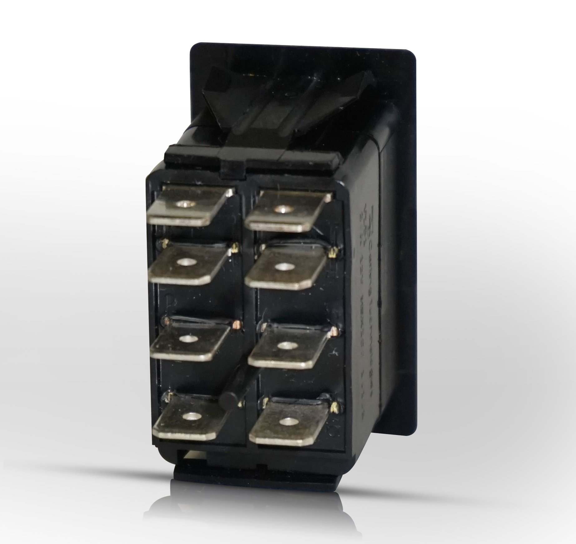
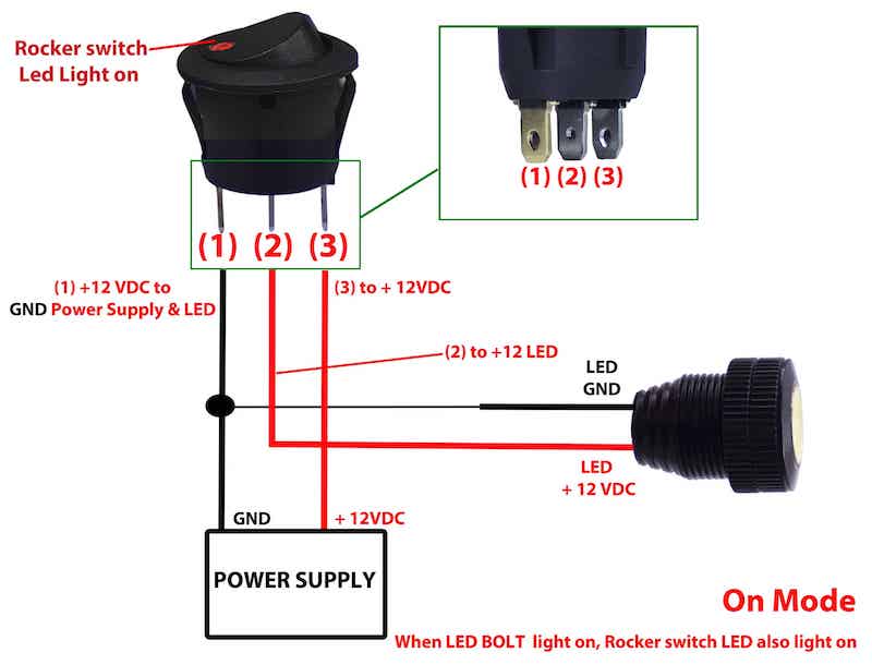
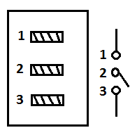
Stuff like reset or keypad buttons. Terminal 1 is connected to one load or accessory terminal 3 is connected to another load or accessory.

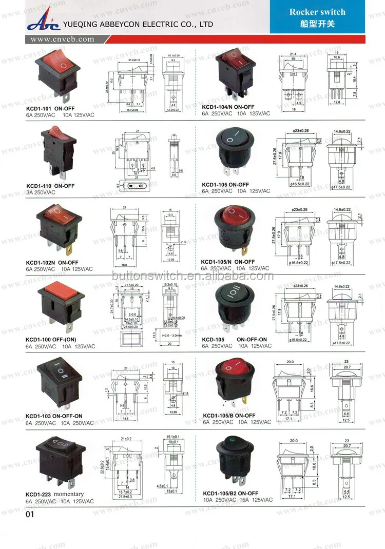
Carling Rocker Switches
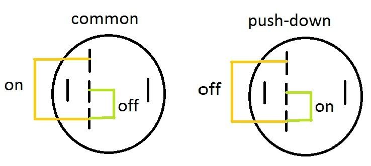
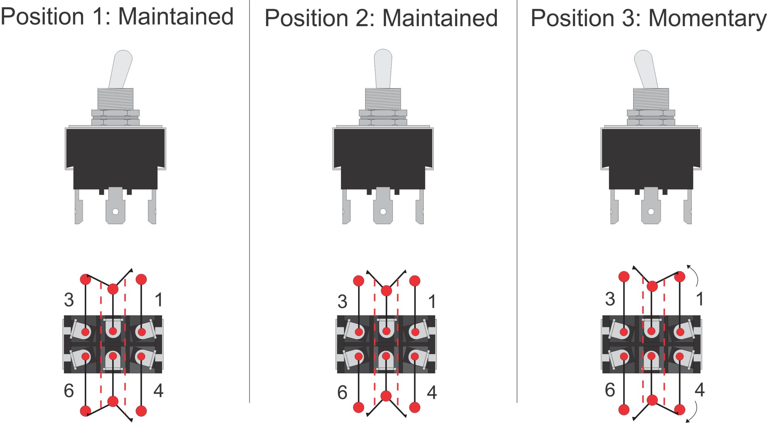
Momentary toggle switch wiring diagram. Most often momentary switches are best used for intermittent user input cases. Assortment of on off on toggle switch wiring diagram. Typically these switches have a really nice tactile clicky feedback when you press them. A dpdt toggle switch has 6 terminals. Push button switches are the classic momentary switch. How to wire a on off on toggle switch diagram.
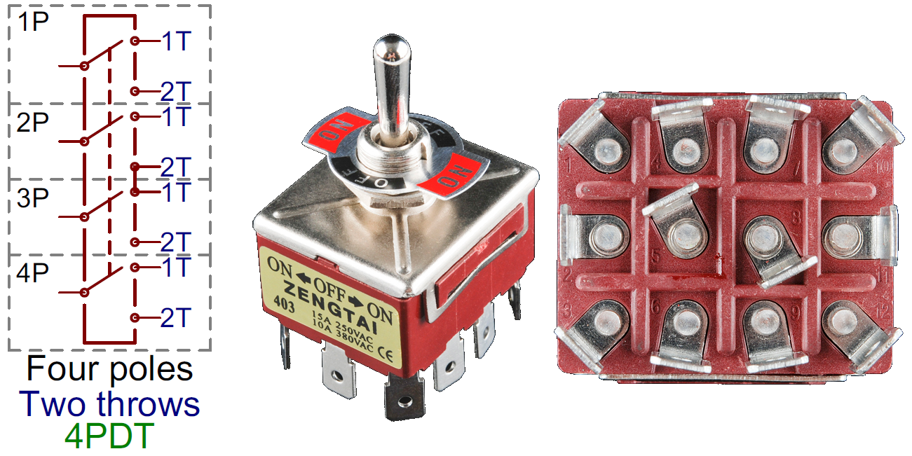
The switch is always making one of the two connections and flips between them. A wiring diagram is a streamlined standard photographic representation of an electrical circuit. A double pole double throw switch is used for this purpose but you have to wire it up correctly. 2 methods are explained with associated wiring diagrams. Examples of momentary switches push button. This wiring diagram applies to several switches with the only difference being the color of the lights.
Terminal 2 is connected to power. Wire a dpdt rocker switch for reversing polarity. The vmdj is a unique dpdt momentary rocker switch. In this video i give you the characteristics of a dpdt switch and how to wire. Below is the schematic diagram of the wiring for connecting a dpdt toggle switch. This is how you wire a double pole double throw dpdt switch.
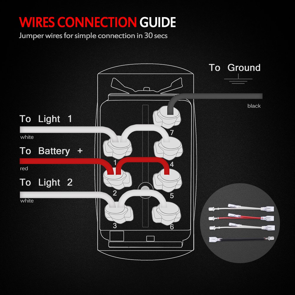
Nov 4 attachment i have a 7 pin on off on rocker switch that i am trying to wire up i have a diagram that i have attached that came with it and awaterwich 7 pin momentary winch in out rocker toggle switch waterproof dc 20a 12v10a 24v black shellon off on dpdt illuminated rocker switch for auto truck boat marine off road winch. Typical wiring diagrams for push button control stations 3 genera information at each circuit is illustrated with a control circuit continued schematic or line diagram and a control station wiring diagram. The wiring diagram below will demonstrate how to to wire and power this 12v 20amp on on off 3. Terminals 3 and 4 represent the toggle switch. These terminals receive the power necessary to drive the loads on terminals 1 and 5 and 2 and 6. We will now go over the wiring diagram of a dpdt toggle switch.
L the schematic or line diagram includes all the components of the control circuit and indicates their function. When you need to control a dc motor such as a dc linear actuator you usually need to be able to swap the polarity on the wires going to the motor. Here is a diagram of a spdt toggle switch. Shown can be a 6 for white c for red or x for blue. It reveals the components of the circuit as simplified forms and also the power as well as signal links in between the devices. Quentacy 19mm 3 4 metal latching pushbutton switch 12v buy quentacy 19mm 3 4 metal latching pushbutton switch 12v power symbol led 1no1nc spdt on off black waterproof toggle switch with wire socket plug blue how to wire a 3 way switch wiring diagram how to wire 3 way light switches with wiring diagrams for different methods of installing the wire.
Gallery of Momentary Toggle Switch Wiring Diagram