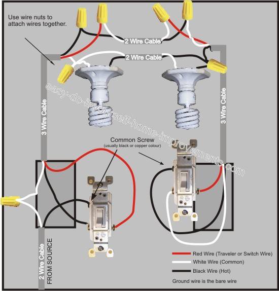
It shows the components of the circuit as simplified shapes and the capacity and signal friends between the devices. Wiring a light switch wiring a light switch diagram 1.
Adding An Extra Light From A Light Switch
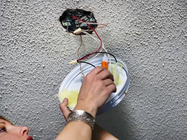
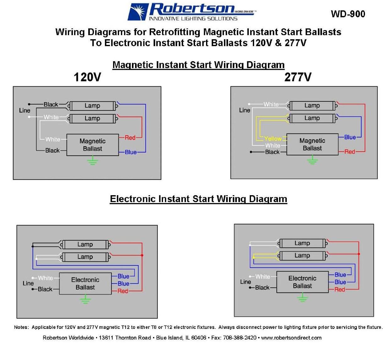
4 wire light fixture wiring diagram. Wiring a diagrams for lights and switches. Fluorescent ballast wiring diagram collections of inspirational wiring diagram for fluorescent light fixture. Open the package of wire nuts and installation screws that came with the new light fixture. Wiring diagram for fluorescent lights new wiring diagram for. Electrical circuit electric circuit listing. On a related note if you see an extra black wire in an electrical box separate from another set of.
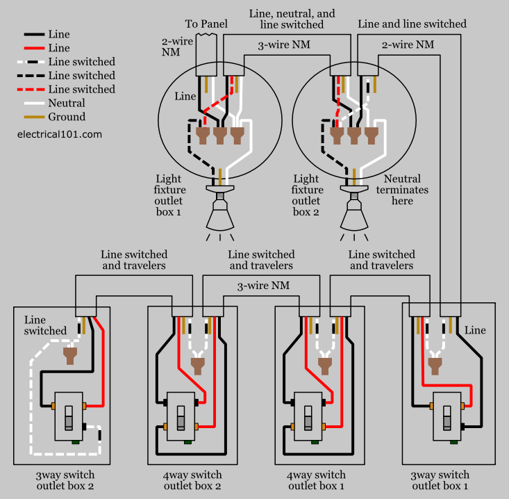
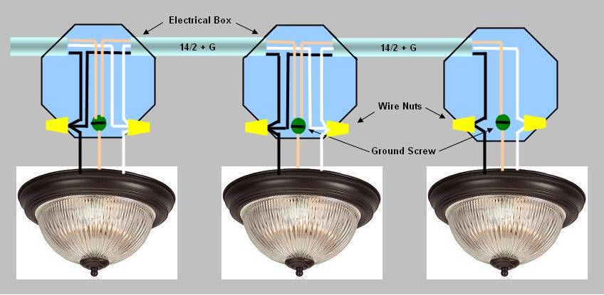
4 way switch wiring with light first. This diagram illustrates wiring for a 4 way circuit with the electrical source at the light fixture and the switches coming after. Two 2 wire cables run between each light fixture after that and 3 wire cable runs from the last light to sw2. Untwist the fixture wires from the house wiring. Jimmy rather than explain it how about seeing it with the help of full color wiring diagrams. It doesnt get any easier that that.
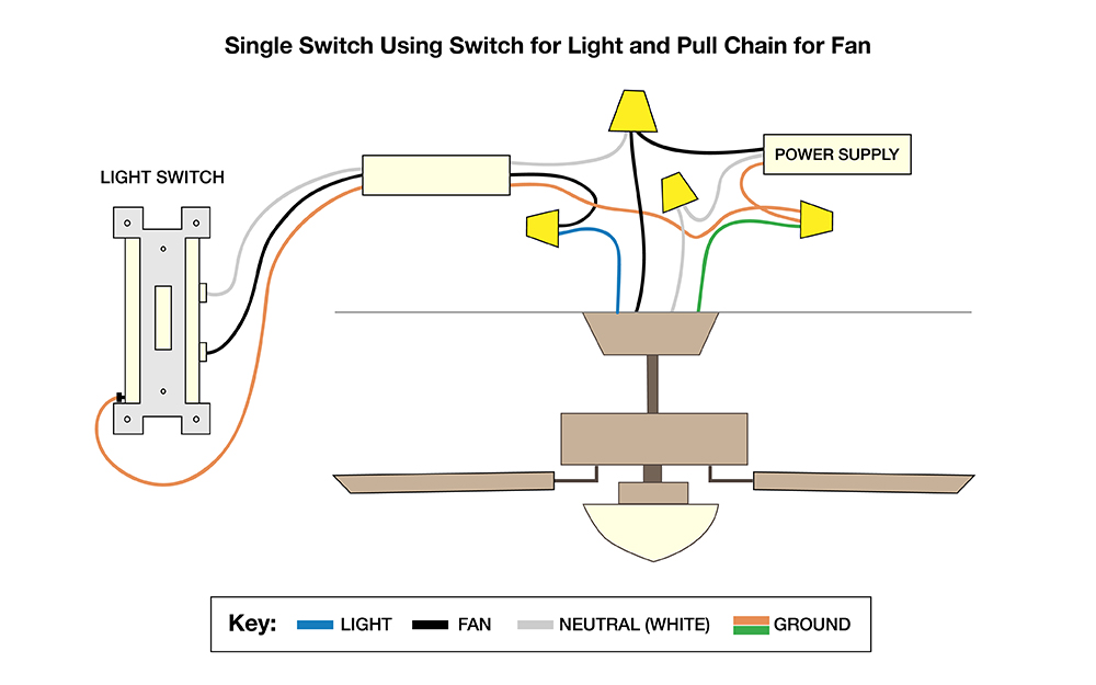
When he did all that his light switch operated the light normally. Dress up a room or give it a whole new appearance by learning how to change a ceiling fixture on your own. 4 wire light fixture wiring diagram wiring diagram is a simplified standard pictorial representation of an electrical circuit. Fluorescent emergency ballast wiring diagram collection. How to wire a t5 ho ballast wire center. At the beginning of the circuit the hot source is connected to the common terminal on sw1.
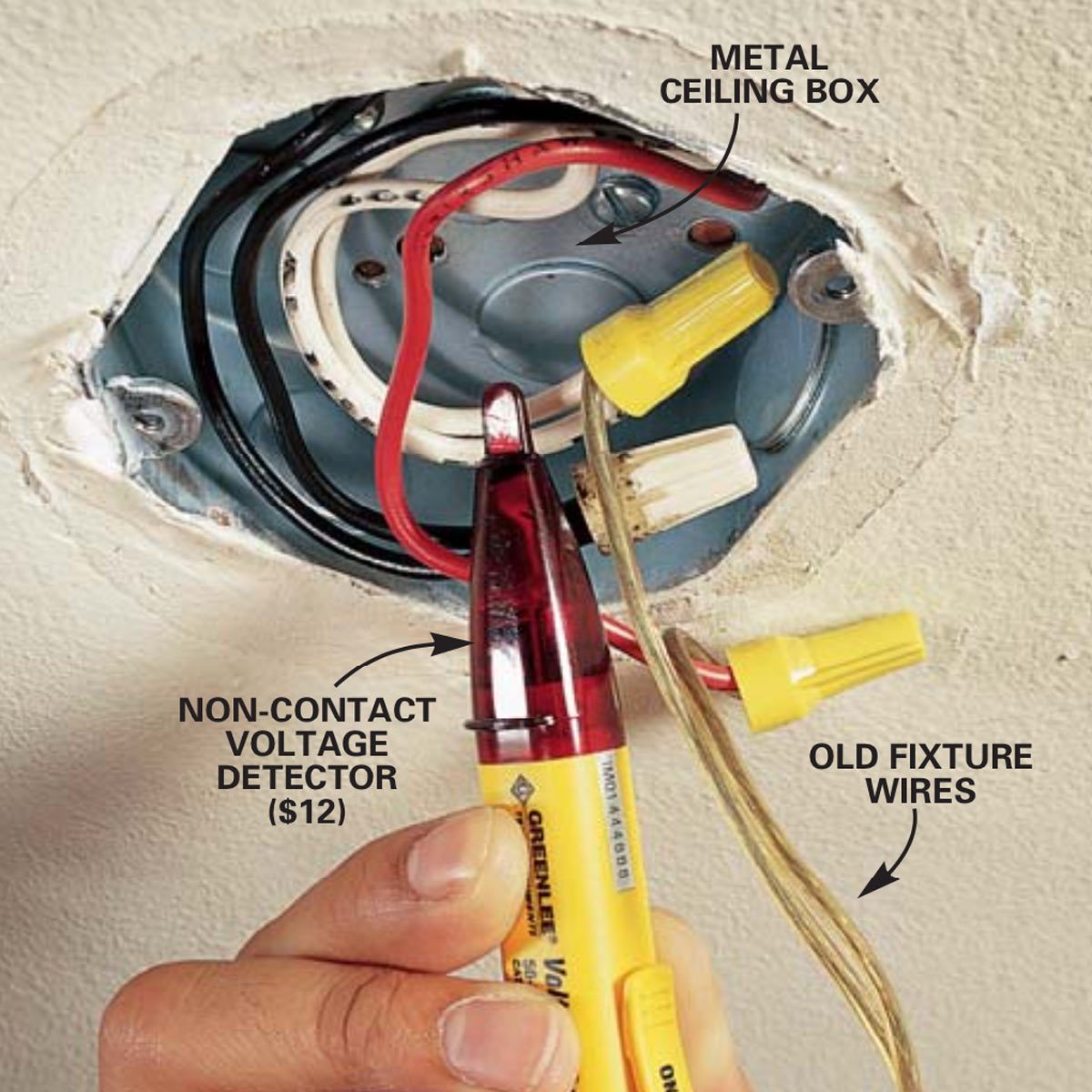
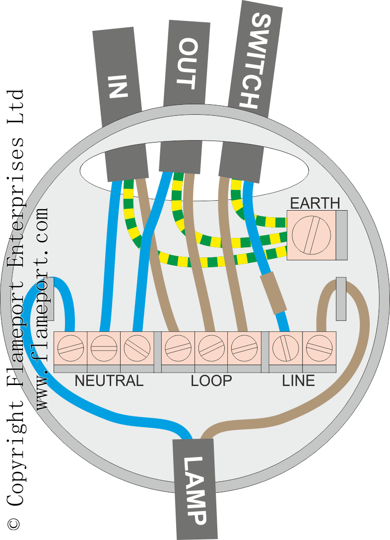
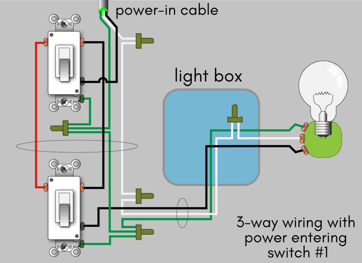
How to wire a ceiling light. Here the source is at the first switch sw1 and 3 wire cable runs from there to the first light l1. A wiring diagram usually gives suggestion more or less the relative position and contract of devices and terminals on the devices to incite in building or servicing the device. When wiring in the 4 way switch it is most simply described as simply cutting the two traveler wires the two wires that go between the two 3 way switches and terminate on each switch and putting two wires from one switch on the top two terminals of the 4 way switch while putting the other two wires from the other switch on the bottom two terminals. Inspect the wiring in the outlet box. I had him leave the black wires in the box tied together but not connected to the fixture.
Align the head of the screw into the wider part of the hole. In general practice the diagram above is most often used and is a good guide for wiring a new 4 way switch circuit. While the light only has a black and white electrical wire some manufacturers include an addition wire. Then i had him connect the black wire on his light fixture to the red wire in the box. Two wire cable is run from the light to sw1 and 3 wire cable runs between the three switches. Most light fixtures will have a keyhole shaped hole.
Gallery of 4 Wire Light Fixture Wiring Diagram


/cdn.vox-cdn.com/uploads/chorus_asset/file/19586349/re_wire_fixture_x.jpg)