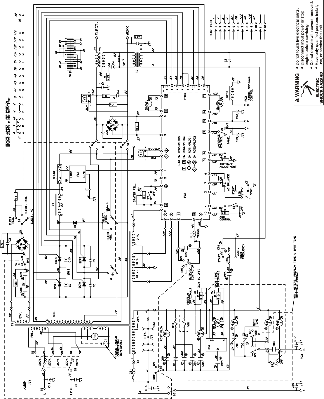
Miller electric manufactures a full line. Circuit diagram for remote hand control used with transformer arc welding power source circuit diagram no.
Miller 14 Pin Connector Wiring Diagram General Wiring Diagram
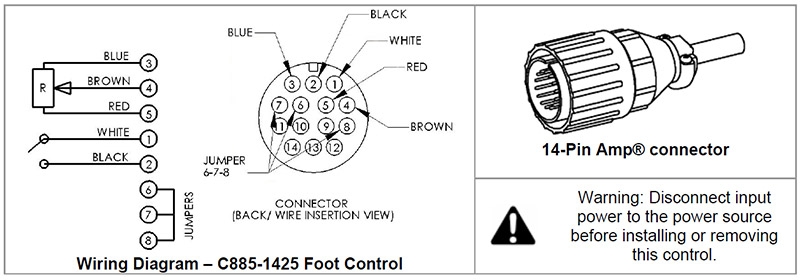
Miller rfcs 14 wiring diagram. The results should be as follows with a smooth change in output as the pedal is pressed. Replaces miller rfcs 14 pn 043554 rfcs 14 hd pn 194744 and hobart pn 043554. Sa 094 231 a diagram 5 3. Beware of electric shock from wiring. For miller welders wiring diagram and test instructions how to check the potentiometer. This is the fix for a miller rfcs 14 hd.
Om 844 page 7 section 3. Rfc 14 rfc 23a rfc 23ag rfcs 23 rfc 23gd25a. Both do the same job. The newer lower plastic rfcs 14 uses a small 2 watt potentiometer. Miller electric rfc 14rfc 23arfc 23agrfc 23gd25arfcs 23 owners manual. Circuit diagram for rhc 3 gd25b circuit diagram no.
Arc not stopping help 10 code foot pedal code high frequency starter on. Electric shock can kill. How to identify the 14 pin connector on your machine. Remote contactor control and re mote amperage or voltage control. Disconnect input power before installing this kit. Using a multimeter on the ohms setting check pins c d and e at the end of the plug with the pedal unplugged.
Sa 150 671 diagram 5 2. Wear a safety harness if working above floor leveldo not touch live electrical parts. Im not sure if this may fix other models. Reinstall all panels and covers. Rfcs 14 and rfcs 14hd models circuit diagram for rfcs 6m models 208 615 b. Tig foot control pedal for miller and hobart tig welders.
The rfc 14 was the original 14 pin control built in the same metal box as the rfc 23a and using the same size resistor with the sliding brush. Normally of the machine has a pilot light that lights when the machine is on. Wire welding the wire wire reel drive roll housing and all metal parts touching the welding wire are electrically live. Welding generator circuit diagram andor instruction manual. For miller solid state power sources after serial number jk674521. Circuit diagram for rhcs 3 circuit diagram no.
Symptoms that this fix may cure. A miller group ltd company po. Pins c e blue brown 1000 ohms. Box 1079 appleton wi 54912 usa. With the machine turned on the cooling fan may or may not run with the machine on. Incorrectly installed or improperly grounded equipment is a hazard.
Works with any miller tig welder equipped with a 14 pin remote receptacle for foot controls. With a meter on ac voltage check between pins a b. Miller style 14 pin receptacle diagram. Sa 094 232 a diagram 5 4.
Gallery of Miller Rfcs 14 Wiring Diagram