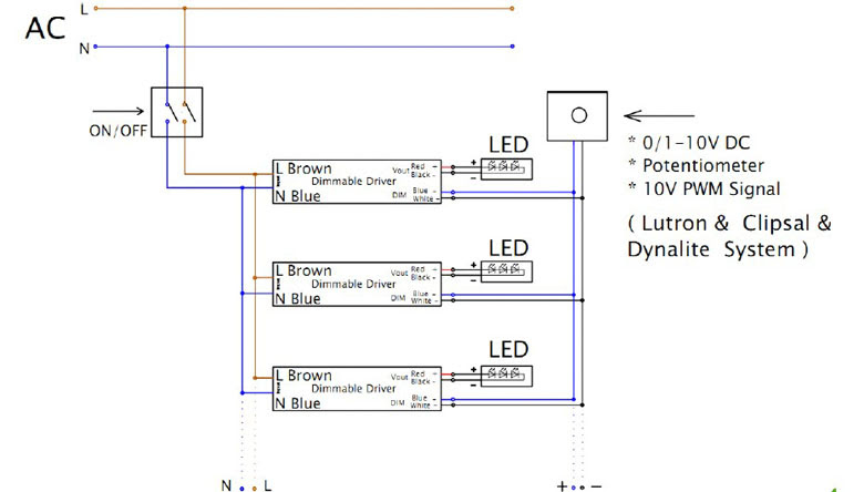
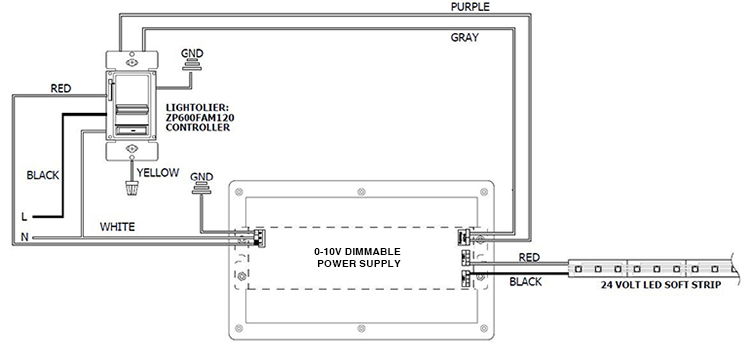
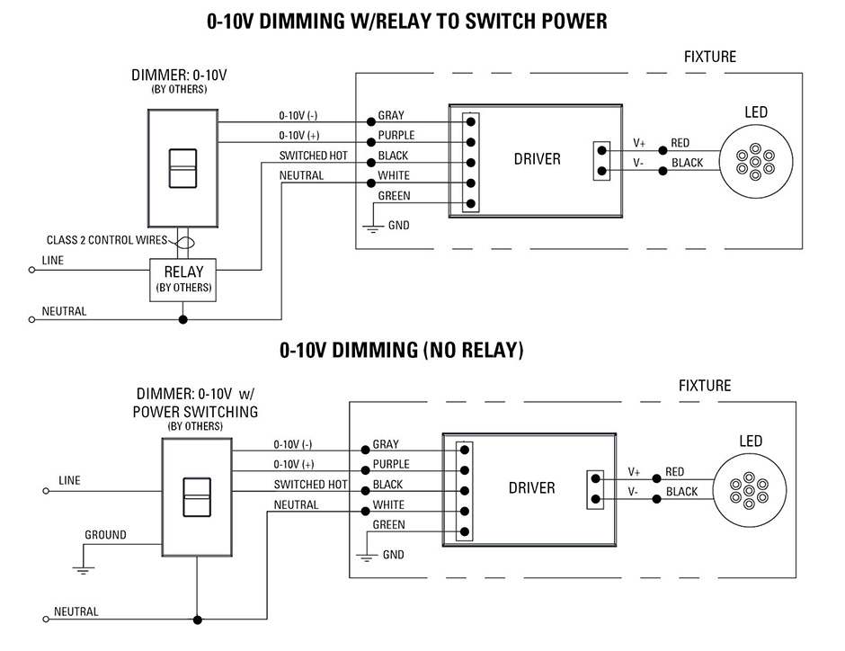
Switched hot black switched hot red typical low voltage dimming wires purple gray typical electrical panel. Wiring diagrams dimming with onoff control wiring diagram using relay 0 10 v ballastdriver white white red red red.
Mega Supply Store Llc Lutron Page 282 Created With
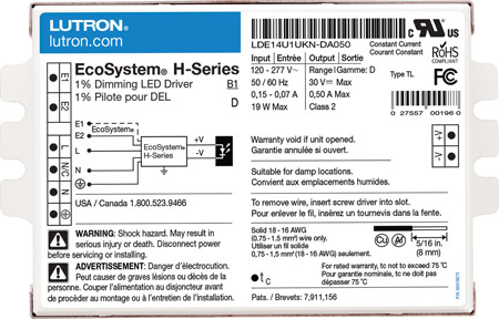
Lutron 0 10 volt dimmer wiring diagram. 5 10 15 20 25 30 35 40 45 50 55 0 switch sensor. Wellborn collection of 0 10 volt dimming wiring diagram. September 10 2018 by larry a. 0 10 v preset dimmer for use with. 1 component 3 components budget friendly costly 20 minutes 5 10 15 20 25 30 35 40 45 50 55 0 50 minutes vs. Operating temperatures 0 c 32 f to 40 c 104 f.
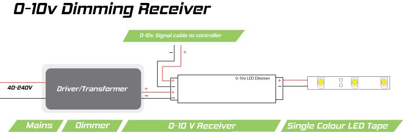
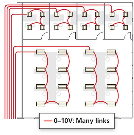
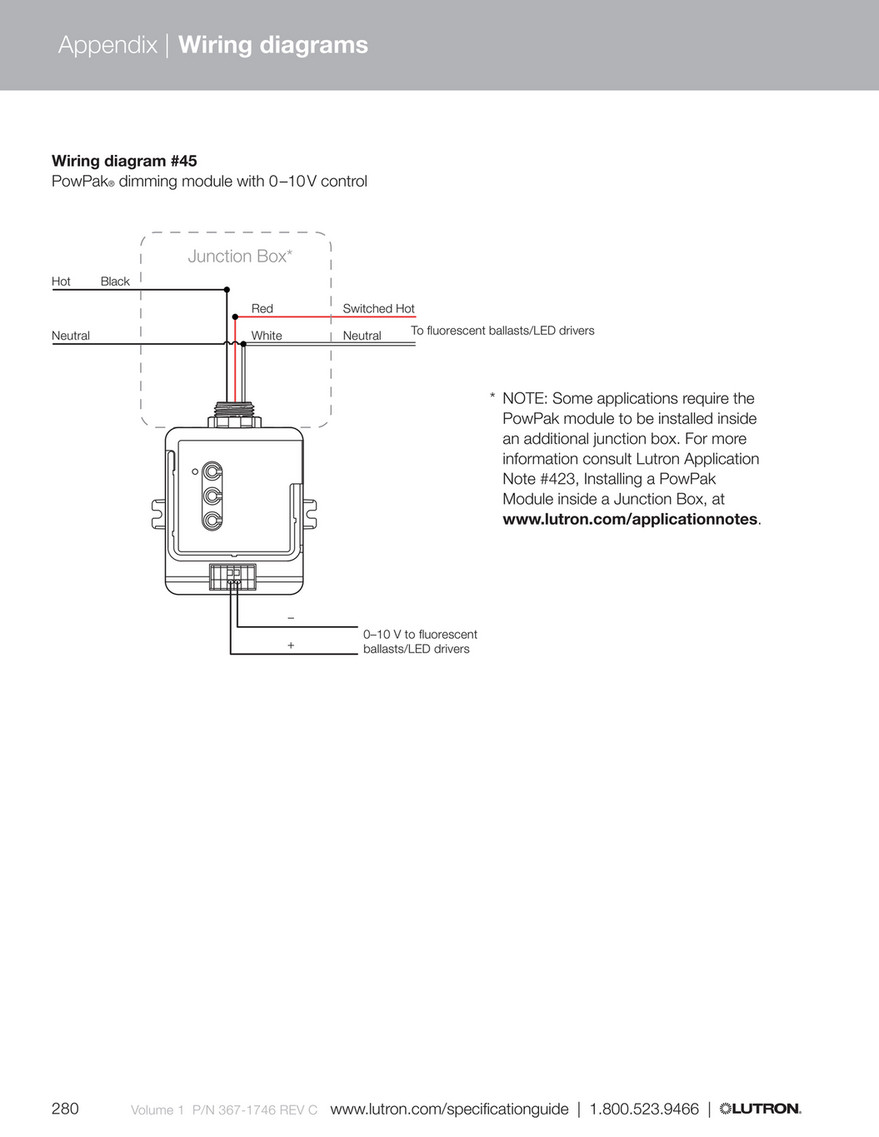
Powpak dimming module with 0 10 v control the powpak dimming module with 0 10 v control is a radio frequency rf control that operates 0 10 v controlled fluorescent ballasts or led drivers based on input from pico wireless controls and radio powr savr tm sensors. 0 10v dimming wiring diagram. Easily monitor control and optimize a lutron control system from any tablet pc or smartphone. A wiring diagram is a simplified standard photographic depiction of an electric circuit. Minimum light level low end shall be adjusted to optimize performance. Typical 010 v dimming sensing switch sensor line voltage wiring low voltage wiring installation time lutron 010 v dimming sensing line voltage wiring low voltage wiring vs.
0 10 v 30 ma switch. Lutron diva dvstv v dimmer for fluorescent and led the lutron diva dvstv is a v dimmer that easily lutron dvstv v installation instructions. Electrostatic discharge tested. 0 10v dimmer switch leviton ip710 lfz or equal. It shows the elements of the circuit as streamlined forms and the power and signal connections between the devices. 0 10 volt lighting control devices package contents and parts identification figure a operation the 0 10 volt low voltage lighting control provides dimming control for 0 10 volt compatible led drivers fluorescent ballast and hid ballast.
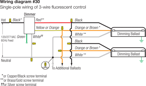
Wiring diagram 1 insulating label green ground black white red hot black neutral white line 120277vac 60hz dimmer gray yellow to lamps red blue 0 10 vdc ballast yellow red 1 3 7 matching remote additional neutral wire 2 dimmer 2 3 4 red violet white yellowred gray black green 6 5 1 wiring diagram 2 green ground green ground white. 010 v is quickly becoming one of the more popular dimming technologies with wired occupancy sensors for v. 24 v 100 ma performance power failure memory. Each feature is designed around what is most important to you how well your building is working. Enviroment for indoor use only. A typical 0 10v wiring diagram is shown below.
For other types of dimming control systems consult controls manufacturer for wiring instructions. Lutrons new facility management tool empowers you to manage your building from anywhere. Our standard 0 10v dimming driver option is often provided standard check spec sheets and dims down to 10 at minimum light level. Hot black typical 120v or 277v 60 hz neutral white ground ground. The dimming module with 0 10 v control is ideal for. A 0 10v dimmer is considered analog dimming and all usai 0 10v dimming options are considered to be sink type dimming.
Gallery of Lutron 0 10 Volt Dimmer Wiring Diagram