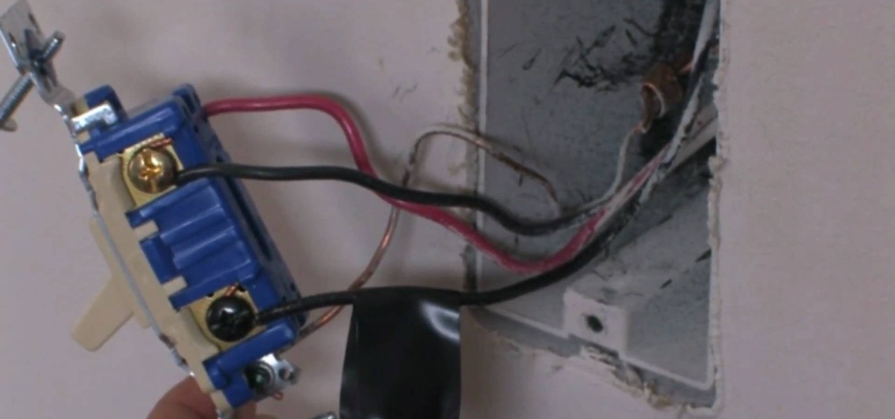
This guide demonstrates how to wire a lutron occupancy sensor with the ntstv dv or dvtv in the same installation. Adjoining wire routes could be revealed roughly where specific receptacles or components must be on a common circuit.

Bbeveledeveled 1020 Bbasica Sic Project Information Pages 1
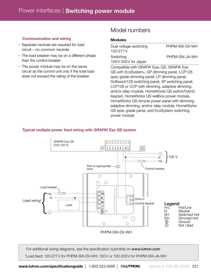
Lutron pp dv wiring diagram. For lutron power pack specification please see lutron pn 369544. Lutron dv 600p wiring diagram whats wiring diagram. Maximum of 60 lutron 0 10 volt electronic fluorescent dimming ballasts. Each feature is designed around what is most important to you how well your building is working. Power pack units dv and 347h power up to 3 total devices including occupancy sensor units and. If wiring for onoff and dimming the low voltage ballast control must be used with the lutron pp 20 power pack.
A wiring diagram is a form of schematic which uses abstract pictorial symbols showing all the interconnections of components in a system. Pp and upp series power packs provide both the 24 v power supply to operate lutron. Model number operating voltage wiring load switching capacity 010 v sink capacity dvstv xx 2 120 277 v single pole 3 way 5 8 a 50 ma dvstv 453ph wh 1 dvstv 453ph. 4 a lutron power pack pp dv or pp 347h is required for switching ballasts and drivers. Easily monitor control and optimize a lutron control system from any tablet pc or smartphone. Requires the use of a lutron pp series power pack eg pp dv or pp 347h.
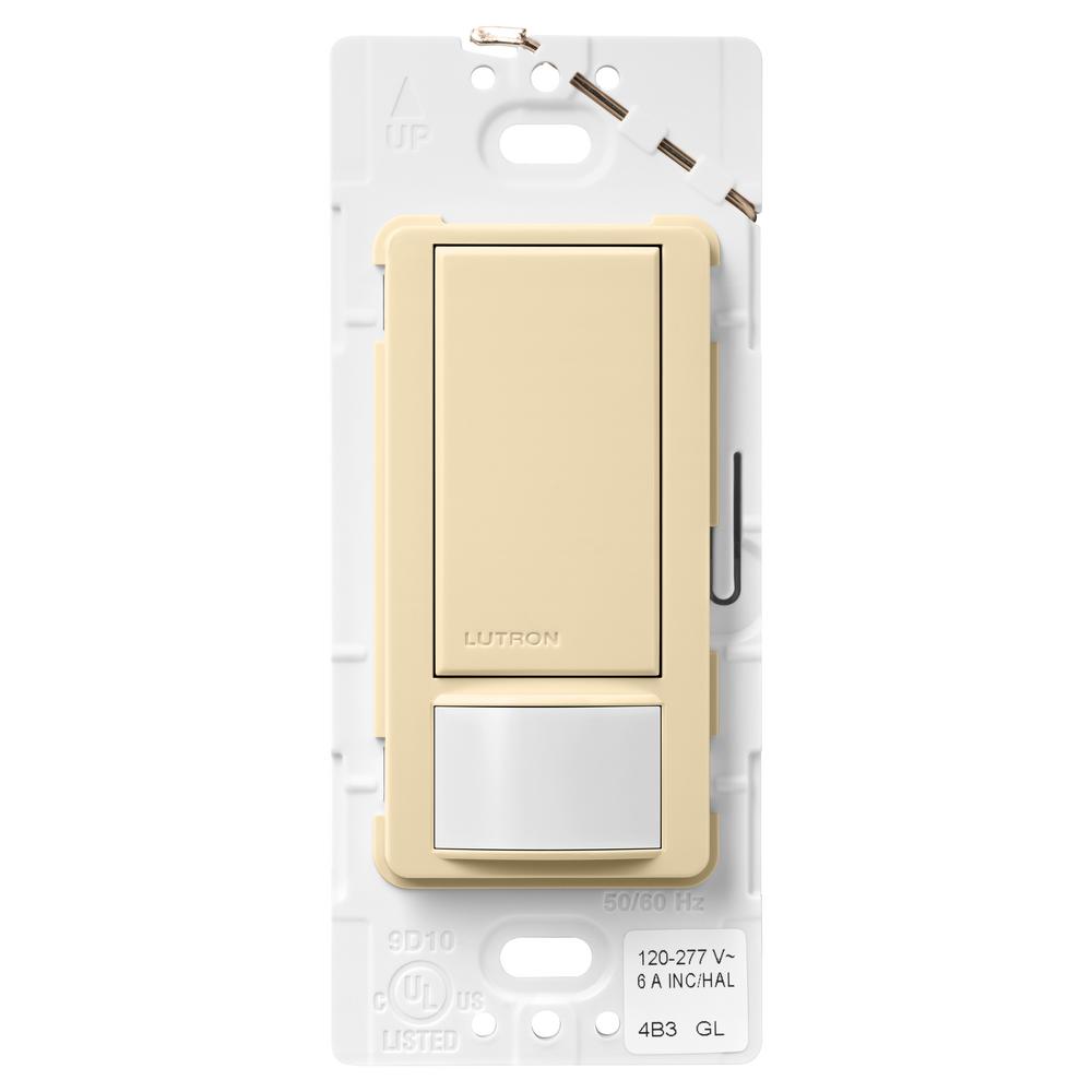
Lutron dv 600p wiring diagram download building wiring layouts reveal the approximate places as well as affiliations of receptacles lights and also permanent electric solutions in a building. Lutron pp and upp series power pack keywords. Lutrons new facility management tool empowers you to manage your building from anywhere. Lutron pp and upp series power pack pp upp power pack pp dv upp dv pp dv m upp dv m pp 347h pp sh upp sh spec submittal 369544g 369 544g 369544 369 544 created. Wiring 3 sensors with power pack pp dv upp dv or pp 347h 1 1 maximum 3 occupancy sensors can be used with pp dv upp dv or pp 347h. The ntstv dv and dvtv are 010 v controls for compatible 010 v led drivers and fluorescent ballasts.
Please refer to the uorescent dimming systems selection guide pn 366 002 or lutron. Model number operating voltage wiring load switching capacity 010 v sink capacity dvstv xx 1 dvscstv yy 2 120 277 v single pole 3 way 3 8 a 50 ma dvtv xx 1 dvsctv yy 2. Do not connect this control to line voltage. Always turn power off and lock out during unit. Wire according to appropriate wiring diagram for your product see next page. The lutron rmj 5t dv b powpak dimming module can be used to achieve wireless control of 0 10 volt dimming drivers for very large installations.
6 a lutron power pack pp dv or pp 347h is required for switching ballasts and drivers.
Gallery of Lutron Pp Dv Wiring Diagram