This makes the procedure for assembling circuit simpler. 1 shows the maf sensor made by bosch and fig.

Toyota Sienna Service Manual Mass Or Volume Air Flow Circuit
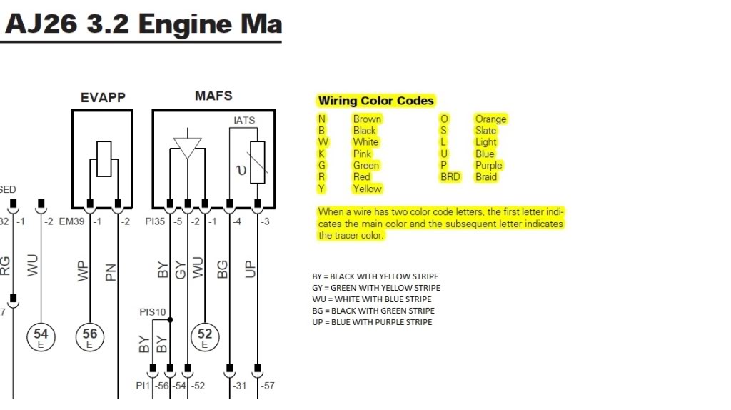
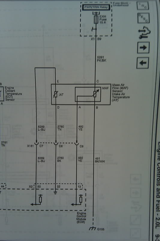
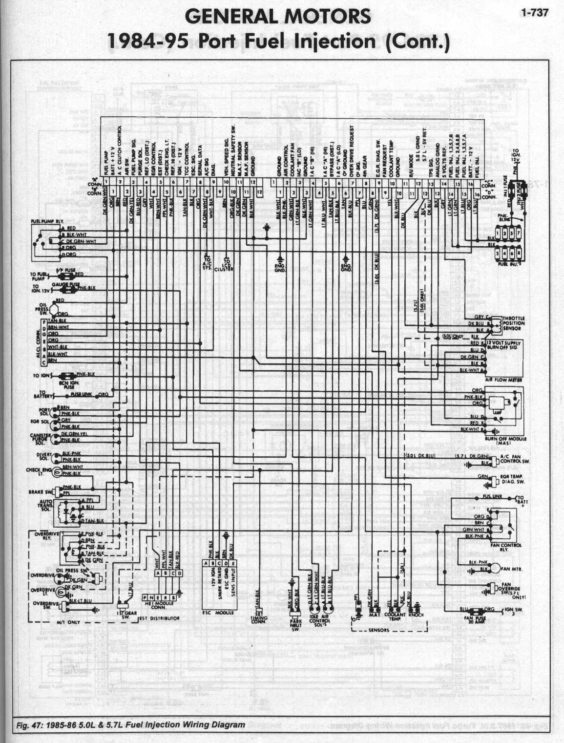
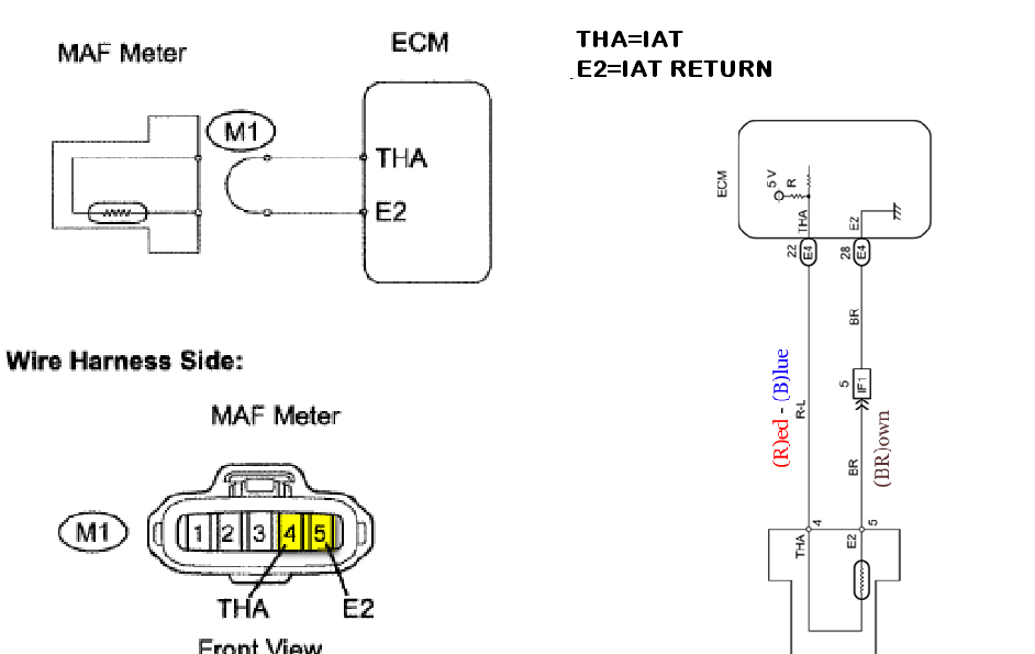
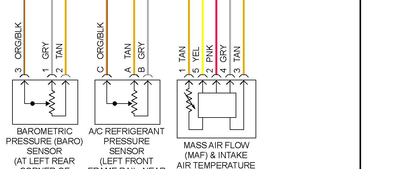
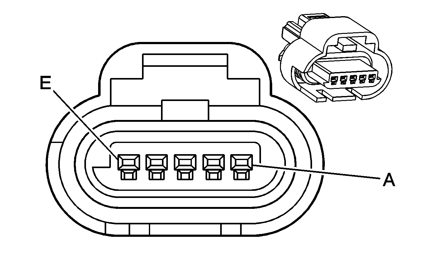
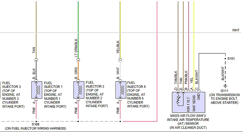
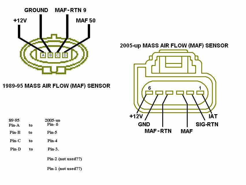
Maf sensor wiring diagram. A mass air flow maf sensor responds to the amount of air flowing through a chamber containing the sensor. If the wires are okay replace mass air flow maf sensor. The following schematic shows a typical circuit diagram of the mass air flow maf sensor system. Maf sensor gets power from the pcm power relay red wire. Maf sensor wiring diagram 19971998 1999 ford 46l 54l. F150 f250 f350 mustang crown victoria.
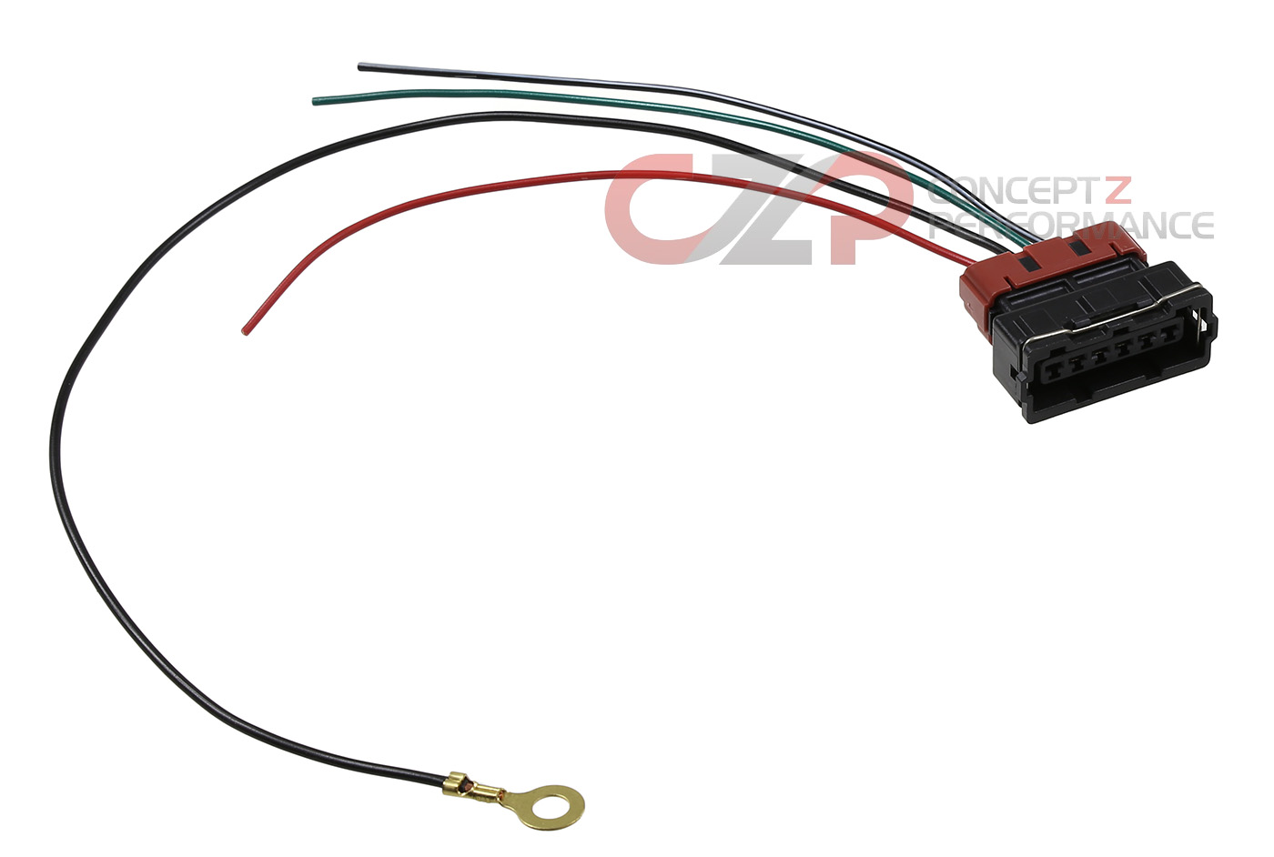
Wiring specialties mass air flow sensor mafs connector 300zx mass air flow sensor wiring diagram the diagram offers visual representation of an electrical arrangement. Each part ought to be placed and connected with different parts in particular way. On the other hand this diagram is a simplified version of this arrangement. If not the structure wont work as it ought to be. Mass air flow sensor wiring schematic. The primary components of the maf sensor are thermistor a platinum hot wire and an electronic control circuit.
The mass air flow sensors converts the amount of air drawn into the engine into a voltage signal. Maf wiring diagram ford maf wiring diagram ka24de maf wiring diagram ls1 maf wiring diagram every electric arrangement is composed of various unique components. The lt blured wire outputs the maf signal to the pcm. Is not attained check the wiring from terminal 3 to fuse panel using an applicable wiring diagram.
Gallery of Maf Sensor Wiring Diagram