Limitorque l120 wiring diagram sample architectural wiring representations show the approximate areas and affiliations of receptacles illumination as well as long term electric solutions in a structure. Table 41 required rating for external wiring up to.
Limitorque Smb Wiring Diagram Limitorque L120 Wiring Diagram
Limitorque actuator wiring diagram. Limitorque drawings allow users to address mov level form and fit engineering questions. Flowserve limitorque mx 20 pdf user manuals. For optional features please refer to page 5. The following control features are included in the basic specification. They contain the mechanical dimension data most commonly needed to ensure that limitorque products fit both the valve topworks and the surrounding space available for mov installation and maintenance. Flowserve limitorque qx pdf user manuals.
Table 58 control module contactor assembly parts list. All l120 units are supplied with 8. Today all heavy duty electric actuators use some device that limits the torque in order to safely operate automated valves and protect people and property. Interconnecting wire routes might be revealed around where particular receptacles or fixtures should be on a typical circuit. Limitorque has evolved over almost 90 years since its strategic introduction of a torque limiting design. Use wire rated at least.
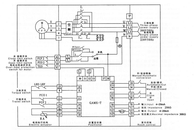
View online or download flowserve limitorque qx user instructions maintenance and spare parts. Flowserve limitorque actuators are available with a wide range of standard and optional features. Figure 37 standard wiring diagram three phase shown. The wiring diagram for all standard mx actuators is shown on page 9. Figure 515 continued 131. Control module contactor assembly and wiring diagrams.
Limitorque mx electronic actuator fcd lmenim2306 06 1013 2. Limitorque wiring diagrams are listed for most standard and optional electricalelectronic configurations of currently supported products. Local control the accutronix control panel includes a red localstopremote selector. 21 calibrate position limits 9. Verify all actuator wiring is in accordance with the applicable wiring diagram national and local codes and table 41. 1 important notes 7 2 quick start 9.
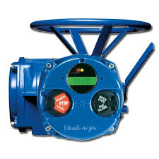
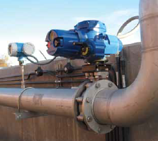
As a result all valve operating components are protected. Limitorque mx series electronic actuator. Consult the relevant wiring diagram for limit switch contact closed generally required if uec 3 family fig 2 development. Limitorque qx electronic actuator fcd lmenim3306 06. Mxa wiring diagrams single phase. Limitorque actuators control the opening and closing of the valve and limit the torque and thrust applied to the valve stem.
Figure 314 standard wiring diagram 25 figure 315 removing outer plastic jacket 26 figure 316 separating cable parts 26. View online or download flowserve limitorque mx 20 user instructions.
Gallery of Limitorque Actuator Wiring Diagram