12 gauge wire minimum 3 4 axle trailers. Keep these instructions with the brake control for future reference.
Cdf7863 Husky Quest Brake Control Wiring Diagram Wiring Library
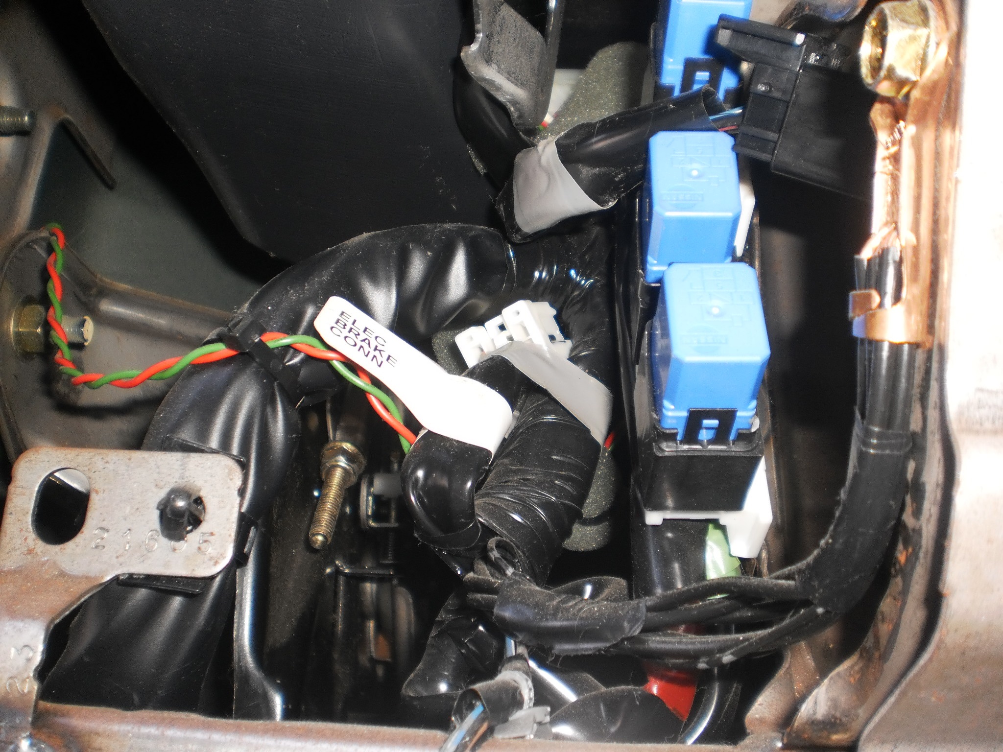
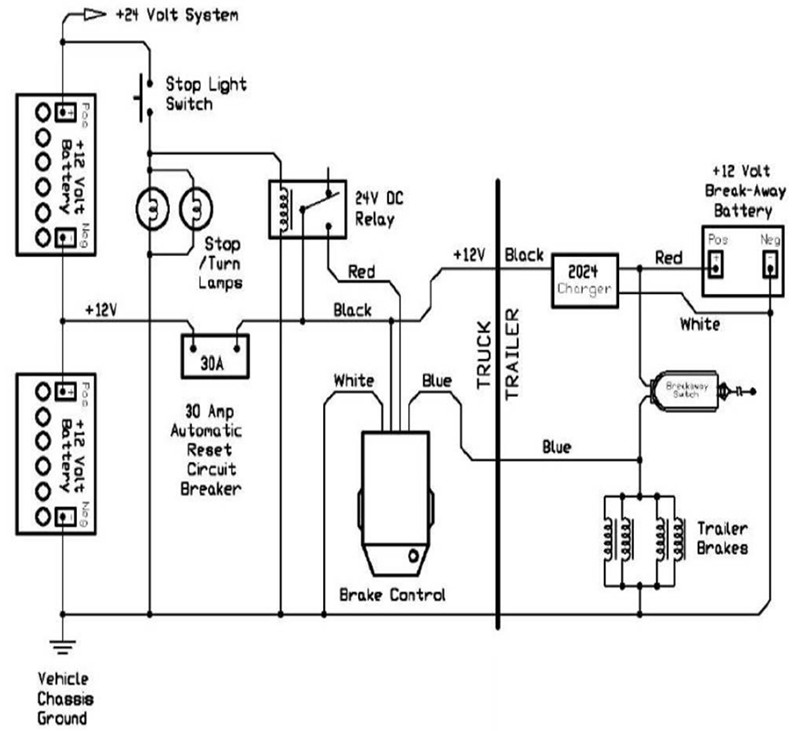
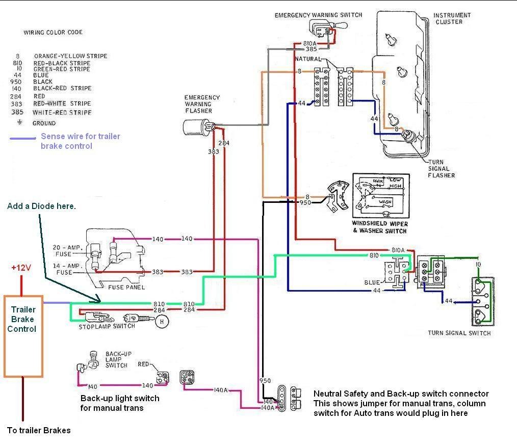
Journey hd brake controller wiring diagram. Wiring instructions for electronic brake controls pn 4399 rev k generic wiring diagram read this first. Splice one blue wire of the break away switch to the electric brake wire coming from the trailer side connector a see diagram on next page. Important facts to remember 1. Read and follow all instructions carefully before wiring brake control. Auxiliary connection is optional it may be connected to any 12v to 24v constant power source or left unconnected. Start the tow vehicle to ensure sufficient battery power is being supplied to the brake control.
1 2 axle trailers. Lesser gauge wire may result in less than desirable braking operation. Connect other blue wire of break away switch to the blue wire labeled brake from the break away box b. Hd electric brake control. Connector identification number from the wiring diagrams to provide a figure nu m ber reference. When wiring the journey electric brake control however crimp style connectors are acceptable in making these connections.
If the distance between the tow vehicle battery and the journey electric brake control exceeds 15 10 gauge wire minimum must used between the positive battery terminal and the brake controls. Break away systems may be added to the service brake circuit. The brake control must be installed with a 12 volt negative ground. 10 gauge wire minimum soldered connections are favorable when wiring the journey hd elec tric brake control however crimp style connectors. Electric brake controller wiring diagram. Minimum wire gauges are as follows.
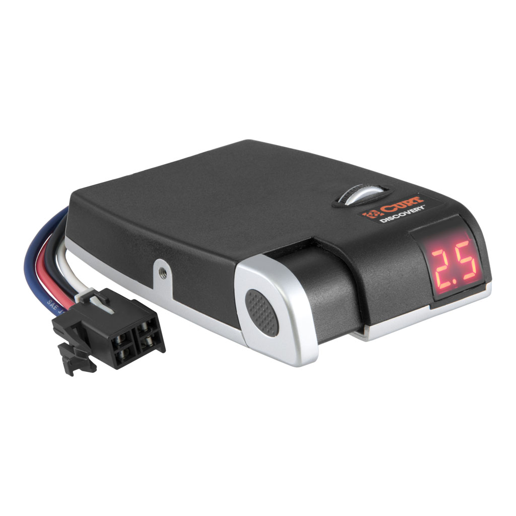
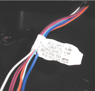
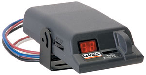
I have the following information on setting up the journey hd brake controller 52740. Elecbrakes is designed to operate 1 to 2 braked axles. Prior to towing the output power must be adjusted for the individual trailer being towed. Connect the desired trailer to the tow vehicle. 1 which identifies the main circuit part of the main. Each wire shown in the diagrams contains a code fig.
Brake controls c climate controls ebl heated mirror.
Gallery of Journey Hd Brake Controller Wiring Diagram