Z wave and c wire power when your thermostat is running on c wire power the z wave radio will stay on and actively help in routing messages within the z wave network. Vivint element thermostat fits seamlessly into your vivint smart home system.
Smart Thermostat Ct100 Program Hvac
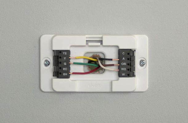
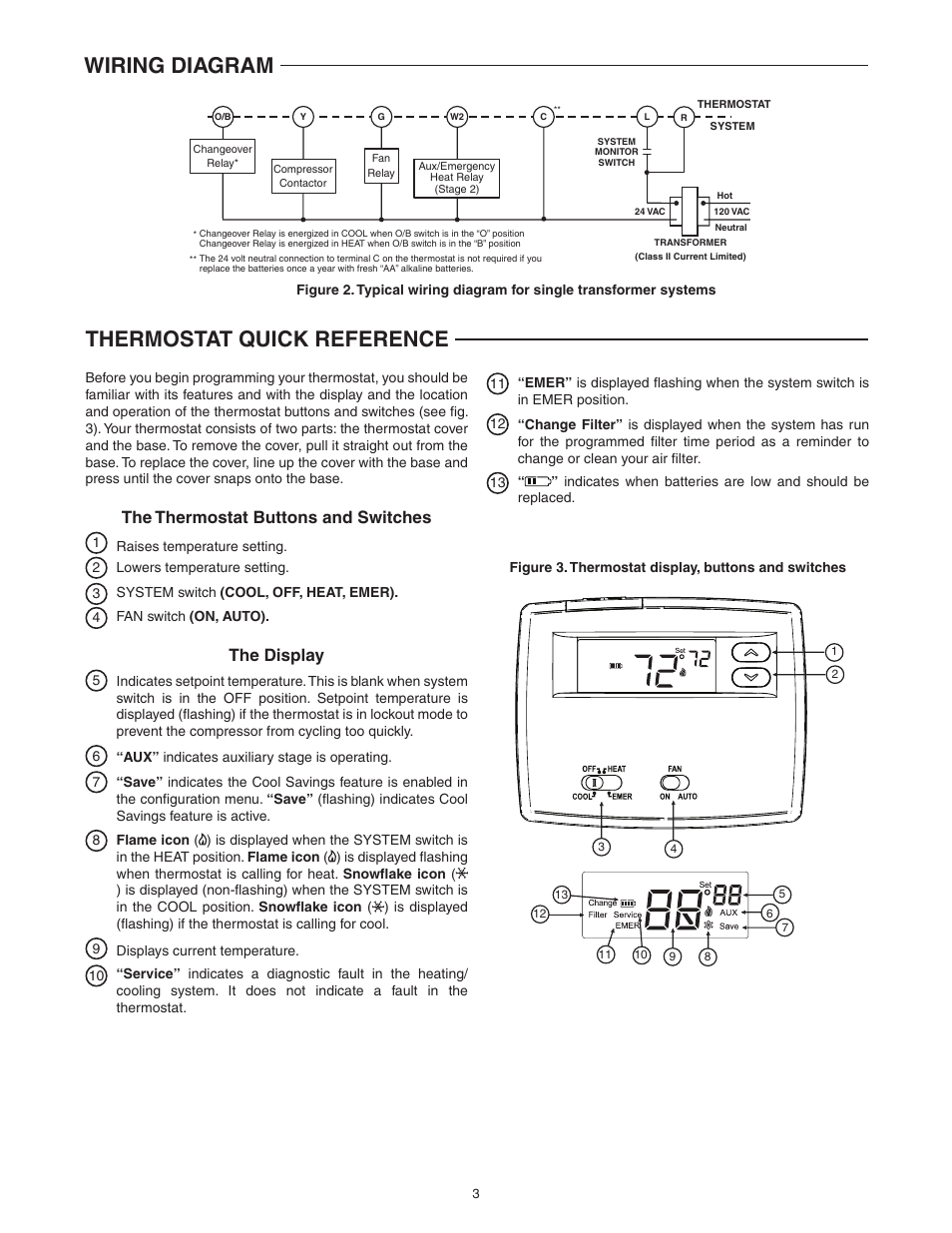
Vivint thermostat wiring diagram. Vivint element ct200 installation guide. Wireless thermostat controls let you start the air conditioning on your way home or keep your home office toasty during a blizzardall from the same mobile app that controls your locks cameras and garage door. Higher amperage may cause damage to the thermostat. Smart home app lost remote access. A wiring diagram is a simplified conventional pictorial representation of an electrical circuit. Vivint thermostat wiring diagram 19082018 19082018 7 comments on vivint thermostat wiring diagram learn how to troubleshoot the problem if you have an element thermostat and a heat pump with auxiliary heat that isnt engaging when it should.
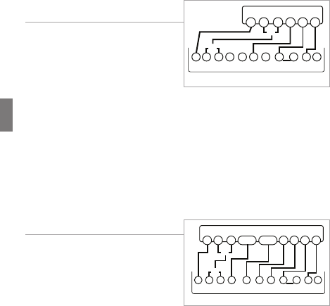
Vivint element ct200 installation guide wiring diagrams step by step wiring diagrams 3 wire heat gas millivolt or hvac system 24vac system power 1 connect the r or rh wire to the rh terminal this connects the heat power c b o w. Connect the w wire to the w thermostat terminal. 3 wire heat gas millivolt or 24vac system. Connect a labeled wire only to a matching lettered terminal. Panel skycontrol reboot. Panel skycontrol disconnected from home network.
It reveals the elements of the circuit as streamlined shapes as well as the power and signal connections between the gadgets. Doorbell camera offline. Page 20 6 if available connect the c wire to the c terminal 7. This connects the heat. If necessary contact customer support for help. All wiring must conform to local codes and ordinances.
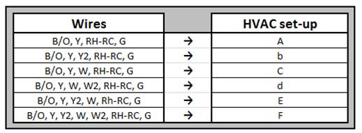
Go to connect your wires on page 9. Vivint element ct200 installation guide. Online account center make a payment. Reference the detailed wire diagram on page 23 to identify your wiring diagram and set up information. Collection of vivint thermostat wiring diagram. Connect the c wire to the c terminal.
Installation guide ct100 wiring diagrams wire reference table possible wires what they control r or v or vr rh and rc single power for heat and cool rh. Each thermostat relay load should be limited to 10 amp. 1 connect the r or rh wire to the rh terminal this connects the heat power 2 connect the w wire to the w terminal this connects the heat 3 if available connect the c wire to the c terminal 4. Powered during network inclusion the thermostat will remain a frequent listening routing slave flirs node until the thermostat is removed from the network via network exclusion. Vivint element 50 pages summary of contents for radio thermostat ct100. This thermostat is designed for use with 3aa alkaline batteries andor 24 volt ac c wire or a 12 24 ac or dc source and millivolt gas systems.
Gallery of Vivint Thermostat Wiring Diagram