If you reverse the wiring at a junction box itll read in the right direction but youll have errors because of the false junctions. Precious viewers when you are hunting the new instrument junction box wiring diagram wiring diagram collection to read this day instrument junction box wiring diagram can be your referred electrical wiring layout.

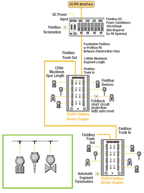
Foundation Fieldbus Ff Segment Topology Segmentation
Instrument junction box wiring diagram. Assign tags to iom channels. Wiring harnesses are joined by using a multiple plug and receptacle connector block or a terminal post chassis junction block. Every instrument in a loop drawing has an input calibration and an output calibration specified for the instrument. Jlr 16 00 211e by appointment to her majesty queen elizabeth ii manufacturers of daimler and jaguar cars jaguar cars limited coventry by appointment to his royal highness the prince of wales manufacturers of daimler. How will a field jb of conventional 4 20ma connection look different from that of ff jb. Yeah also several wiring diagrams are used this wiring representation can take the reader heart so much.
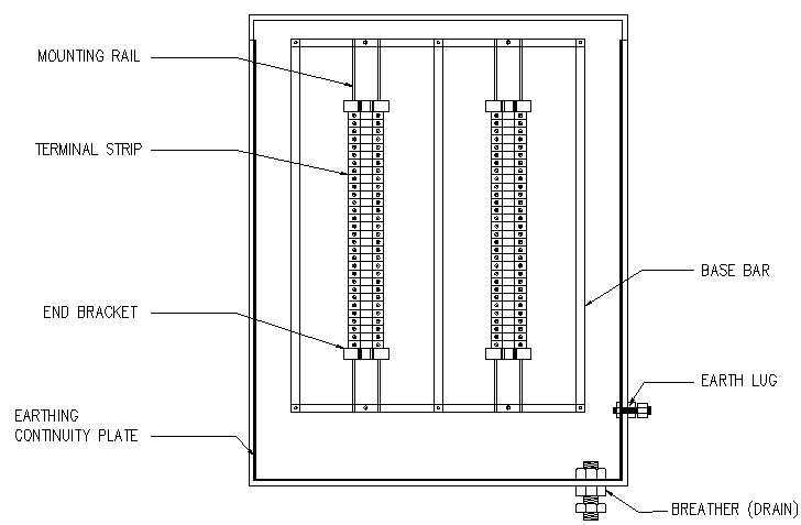
Tag names can also be pasted into a template to produce a junction box drawing that shows interconnect jumper wiring to ftas. To avoid these problems we use marshalling cabinet for terminating these 100 nos main cables. Cable pair and junction box labels are included on loop diagrams. V22231 published by technical communications jaguar cars limited publication part no. Conventional junction box convectional junction box contains terminal strip and earth stripearth bus bar only. Electrical wiring diagrams xj 1a vin.
Cable numbers wire colours junction block numbers panel identification and grounding points are all shown in loop diagrams. In the instrument panel area plastic insulated blade type connectors and screw type terminals are used. Lookup functions show if wire tags exist in the pid registry and if they are assigned to iom modules. The cables from the instruments come to one side of the terminal block and from the other end it goes to the control panel. 73 76 diagrams 73 76 cab interior 73 76 chassis rear lighting chassiscab and stepside 73 76 chassis rear lighting fleetside and suburban 73 76 engine and front lighting 73 76 firewall junction 73 76 instrument cluster 77 80 77 80 250 i6 engine wiring and front lighting 77 80 292 i6 and bbc engine wiring 77 80 sbc engine wiring 77 80 cab interior. A junction box is an intermediate between instrument and control panel.
Each harness or wire must be held securely in place by clips or other holding devices to prevent chafing of. As i mentioned in previous post cables from the control panel is called primary. Here are some basic wiring diagrams from the reference section of the lesman catalog with rules to follow and some suggestions on specifying the right thermocouple wire. So practically it not possible to directly wire these main cables to analog inputoutput cards. Say we have 100 nos of junction boxes installed that means we have 100 nos main cables are there which are coming from field to control room. Read the rest of this entry.
Instruments field pair core cable from instruments to junction box for transmitters switches valves solenoid valve etc is. A junction box is an electrical box which contains terminal blocks.
Gallery of Instrument Junction Box Wiring Diagram