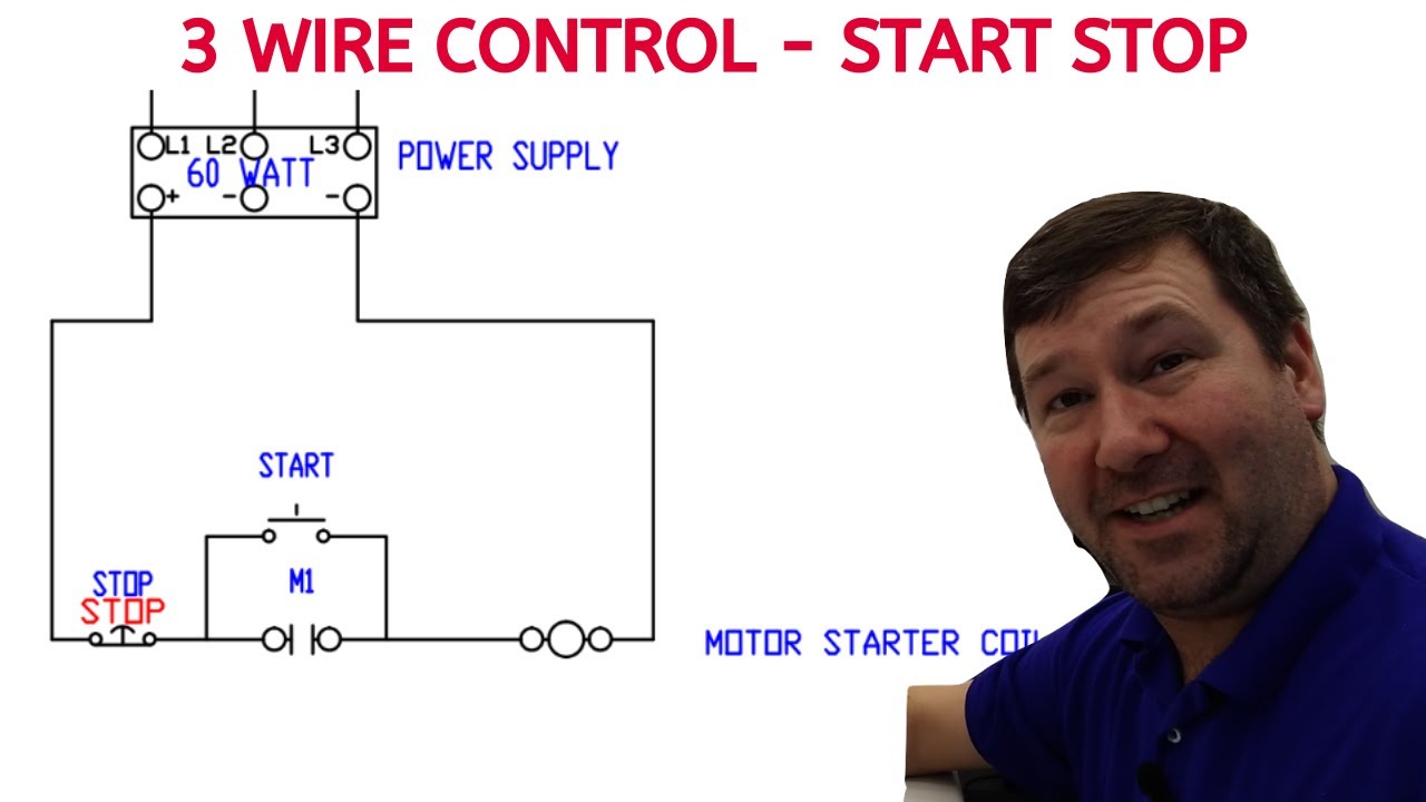
M 2 3 are the holding contacts. 1 j start 2 3 stop i no.

1311 Three Wire Zone Valve Residential Zone Valves Wiring
Holding contact wiring diagram. 2 wire vs 3 wire control. Assume they arent there. Schematic diagrams are used to troubleshoot and install control circuits. Rv holding tank sensor wiring diagram rv holding tank sensor wiring diagram every electrical arrangement is composed of various distinct parts. A wiring diagram is used to represent how the circuit generally appears. Latching relays are also referred to as holding circuits f the trigger power source.
Typical wiring diagrams for pushbutton control stations start stop control wiring diagrams single station basic circuit r 1 klai. Wiring diagrams show components mounted in their general location with connecting wires. 3 wire control circuit. Shows the wiring diagram for a full voltage mag netic reversing starter. Integral 32 and 63 state of auxiliary contacts 53 54 wiring diagrams 55 57 type s ac combination magnetic starters58 59 class 8538 and 8539 58 59. Basic understanding how a holding relay is wired.
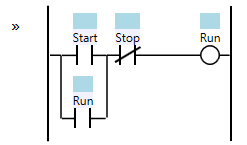
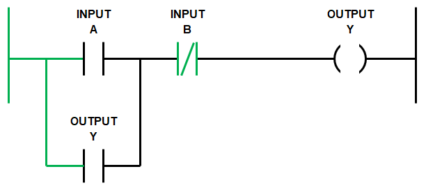
When the reverse contacts r close the motor is connected l1 to t3 l2 to t2 and l3 to t1. The following diagram is also a basic relay but configured in such a way that momentary contact buttons can be used to engage or disengage the relay. How are holding contacts connected. This is a basic lesson on how to hold a relay or latching circuit. 3 wire motor control wiring. 3 wire start stop circuit with holding contacts.
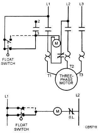
3 wire control diagram. If you push the start button the coil will close the main contacts but if you release the button the coil will open the contacts again. If not the arrangement will not work as it ought to be. 2 examples of wire. An electrically latched relay is a standard relay with one of its own contacts wired into its coil circuit. Scroll down to figure 1a wiring diagram of three phase motor.
I operation depressing the start button energizes coil m hold in contacts m and maintains the circuit after the start button is released. Wiring diagram book a1 15 b1 b2 16 18 b3 a2 b1 b3 15 supply voltage 16 18 l m h 2 levels b2 l1 f u 1 460 v f u 2 l2 l3 gnd h1 h3 h2 h4 f u 3 x1a f u 4 f u 5 x2a r power on optional x1 x2115 v. An external switch initially turns the relay on then it is kept on by its own contact. When the forward contacts f close l1 l2 and l3 are con nected to t1 t2 and t3 just as they would be on a non reversing starter. There are two kinds of latching relays. Air compressor power and control circuit.
An external reset switch interrupts power to the relay which turns it off. Explain the function of a holding contact. Schematics are generally easier to read and understand than wiring diagrams. Each part ought to be placed and connected with other parts in particular manner. I zl ii i i ii i i fo 0. The holding contacts hold the starter closed motor running.
Gallery of Holding Contact Wiring Diagram