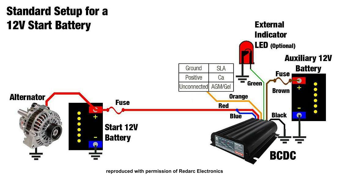
The redarc smart start sbi12 is a microprocessor controlled battery isolator which protects the start battery from excessive discharge while allowing the auxiliary battery to supply charge to non essential loads. The sbi12d has the added feature of allowing charge both ways.

How To Install A Redarc Dual Battery System The Offroad Aussie
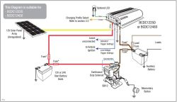
Redarc sbi12d wiring diagram. Redarc recommend using midi fuses along with a quality fuse holder to match. The diagram below. The below diagram shows how to install a gauge using switches to simulate ignition and dash lights providing a simple way to switch the gauge onoff both withwithout the backlight active. The first 100 orders over 50 receive a free stubby holder and sticker pack from built not bought. Check them out today. It is used as a solenoid priority system in dual battery systems and provides 12v dc incorporating 100a of continuous ratings.
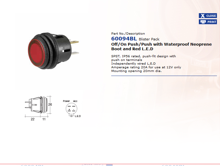
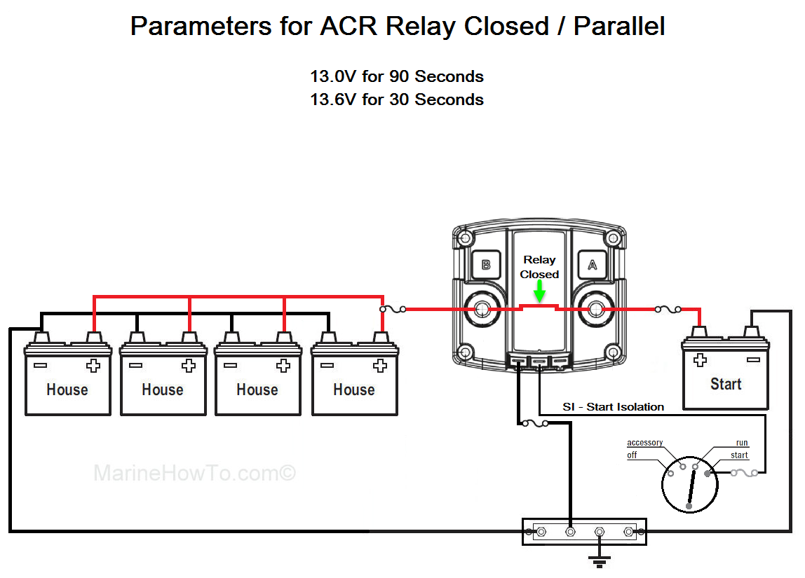
Wiring instructions 3 connect a battery positive cable cable 1 to one of the battery terminals as shown in diagrams b c d. The switch wiring to override the sbi12 needs to be 4mm auto cable. When wiring a gauge into a location other than a car dashboard for example in a caravan park and dash lights may not be available. 6 mount the sbi unit in a convenient location as shown in diagram k. This switch does not connect to the cranking battery positive it is switching earth so one side to earth and the other side to the black wire on the sbi12d. Redarc electronics have a large database of faqs tech tips wiring diagrams and how to guides.
The recommend switch is a 10 amp momentary switch adrian with a momentary switch you can forget to turn it off. This terminal will attach to your auxiliary battery positive terminal. Standard wiring diagrams 3 loads load circuit fuse breaker auxiliary battery start battery fuse sbi 3 3 5 4 6 7 1.
Gallery of Redarc Sbi12d Wiring Diagram