These drivers may be used to drive external relays that can then control. This video will show you how to connect the power and ground wires for a vehicle gps tracking device.
28 Goldstar Gps Wiring Diagram Goldstar Gps Wiring
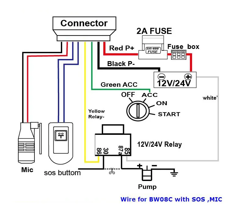
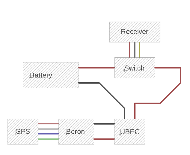
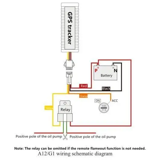
Gps tracker wiring diagram. Here is a link to find vehicle wiring diagrams. Gps and track llc. Securely attach the wiring harness to the calamp and find a constant 12 vdc power source. Vehicle gps tracker with relay installation wiring diagram apr 12 2018 relay connect with a gps tracker is to cut off car engine when the car is stollen or any other situation when the car is urgnetly need to be stopped. Title loan gps tracker. Variety of gps tracker wiring diagram.
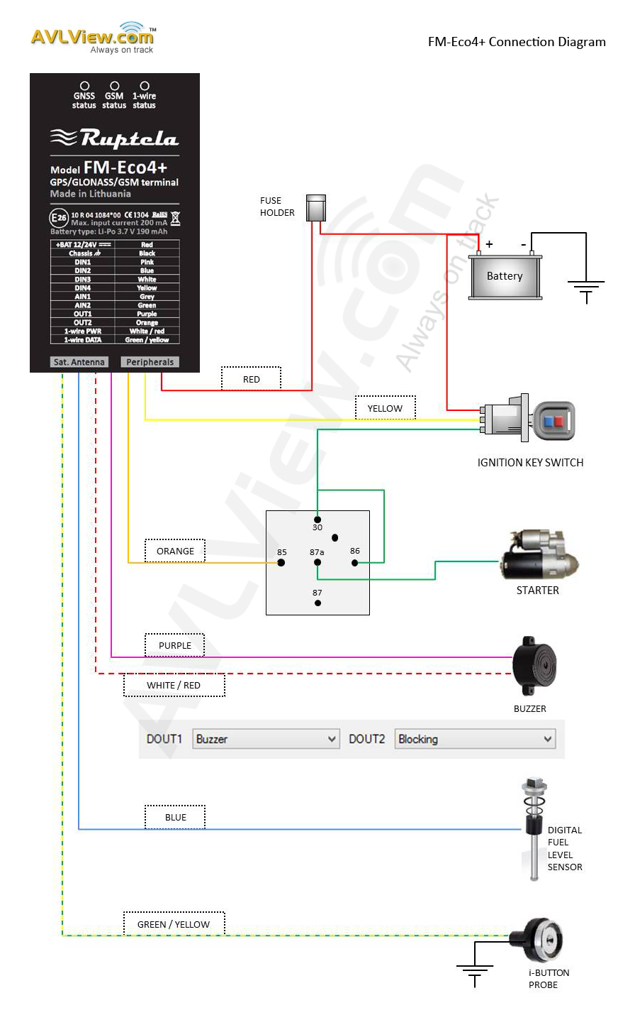
A wiring diagram is a simplified standard pictorial depiction of an electrical circuit. 92nd street suite 130 scottsdale az 85260. Diagram below shows how to connect the inputs. Figure 4 sample input wiring 212 outputs the standard wired devices outputs are designed to drive external relays. To place gps order or more information contact us direct. Gps tracker wiring diagram.
Shopping cart under construction. C4 t1 mini t1. It reveals the elements of the circuit as simplified forms and also the power as well as signal connections between the gadgets. Collection of calamp gps wiring diagram. Our company sells gps tracking devices for 119 that includes service. Our gps tracking experts will send you quotes for the gps tracking devices that best fit your needs.
It reveals the parts of the circuit as simplified shapes and the power and also signal connections in between the tools. July 17 2018 by larry a. Call direct at 602 478. Garmin nüvi 40 gps. Collection of gps tracker wiring diagram. Gps tracker wiring diagram wiring diagram is a simplified usual pictorial representation of an electrical circuitit shows the components of the circuit as simplified shapes and the capability and signal associates in the company of the devices.
These outputs provide a high current open collector driver that can sink up to 150 ma each. Thank you for purchasing your new gps tracking fleet management already scheduled an installation please provide this to the technician. A wiring diagram is a simplified traditional photographic representation of an electric circuit. A wiring diagram is a streamlined standard pictorial representation of an electrical circuit. It reveals the elements of the circuit as streamlined forms as well as the power and signal connections in between the gadgets.
Gallery of Gps Tracker Wiring Diagram