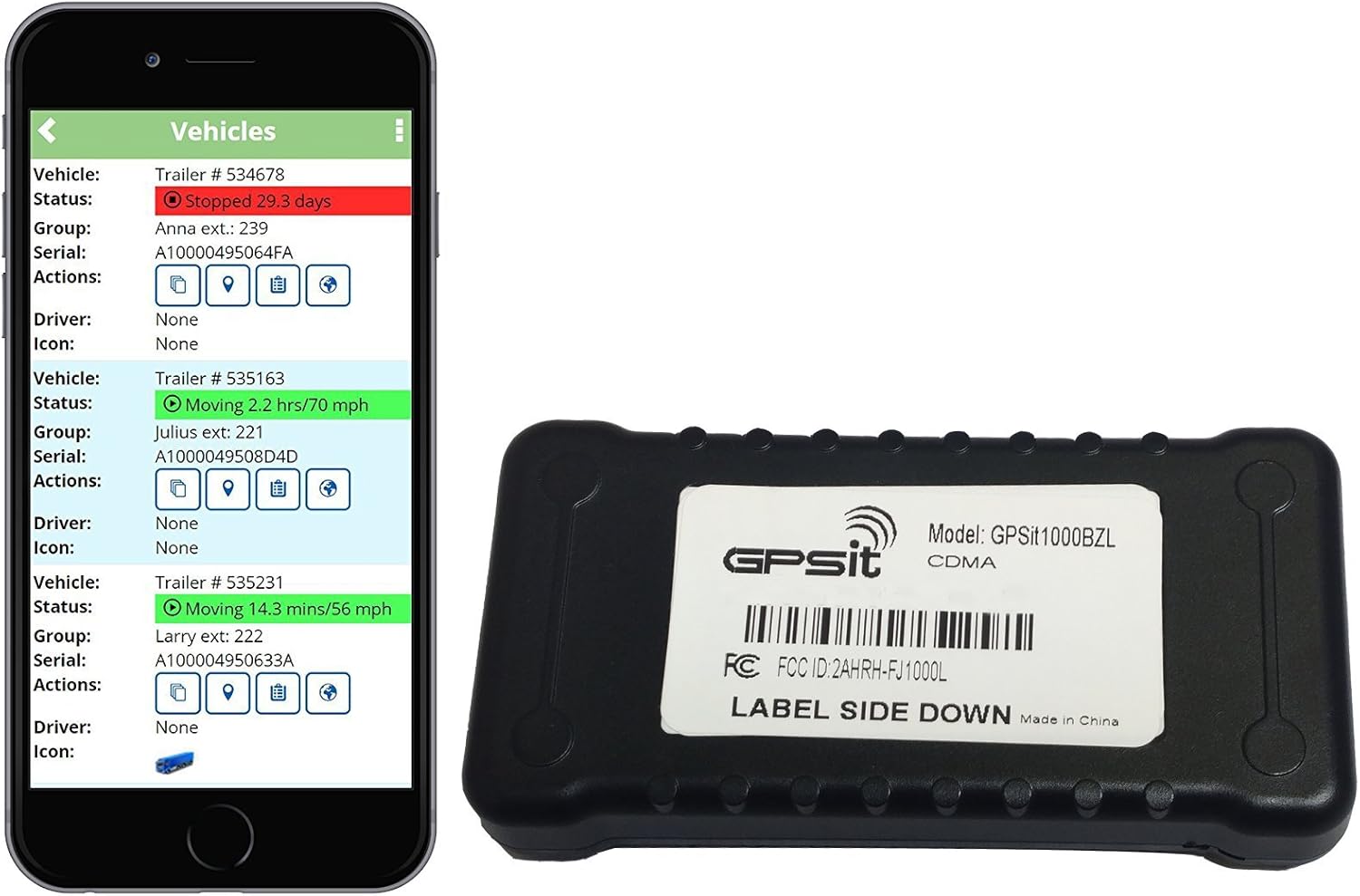
Mounting the device. History gps tracking unit.
Tracker Pro Guide Wiring Diagrams Wiring Diagram
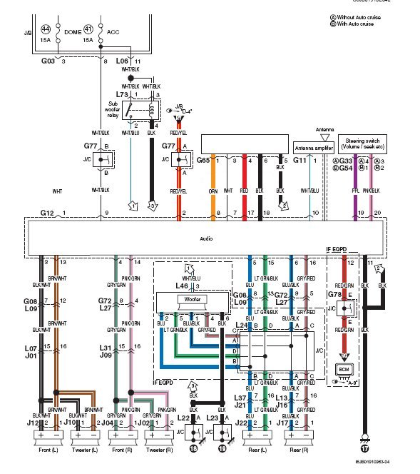
Gps tracker wiring diagram pdf. Use this as a reference when working on your boat wiring. Experience evo the next evolution in gps tracking. Installation made easy tools needed for install. It reveals the components of the circuit as streamlined forms as well as the power as well as signal connections between the devices. And it can be. It reveals the parts of the circuit as simplified shapes and the power and also signal connections in between the tools.
A wiring diagram is a simplified standard pictorial depiction of an electrical circuit. If it is different with its exact current location pay attention to check the. These outputs provide a high current open collector driver that can sink up to 150 ma each. Our gps tracking experts will send you quotes for the gps tracking devices that best fit your needs. Wiring color diagram for tracker and bass tracker boats. When not working his heart out on websites e commerce and programming branson like to enjoy time on the lake.
Figure 4 sample input wiring 212 outputs the standard wired devices outputs are designed to drive external relays. The unit connects to the vehicles electrical system using the included wiring harness part no. Here is a link to find vehicle wiring diagrams. Gps and track llc. Wiring instructions using the included wiring harness part number a 40266 connect the. It can be used on 12 volt dc vehicles.
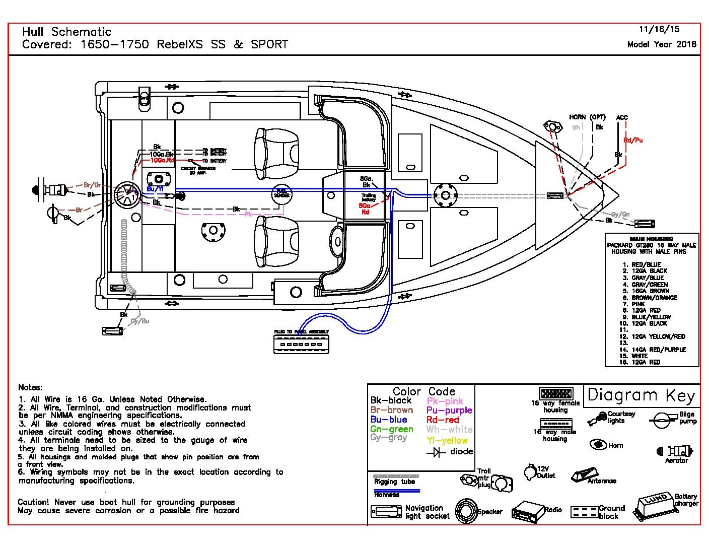
The shadow tracker premier unit uses the vehicles electrical system for its power source. Strip the black wire on the linxup gps device. Tracker boats wiring diagram. The orange wire can be connected to the original car horn. A wiring diagram is a simplified standard photographic representation of an electrical circuit. But the wiring probably isnt long enough to reach the front of the vehicle for power.
It can also be connected to the siren you buy with the tracker. To place gps order or more information contact us direct. And longitude is the position that the tracker received gps signals at last. Locate the vehicles ignition wire reference the vehicles wiring diagram in order to locate. Tracking unit to prevent damage to the connectors. His best times are spent with friends trophy bass hunting in southern.
Collection of bass tracker wiring schematic. Connectors tape and zip ties. In the diagram 2 pages ahead the relay is shown getting power only when the vehicle is cranking. Advantage by procon analytics where automotive telematics meets genuine analytics. This connection serves as a ground for the device. Plus you might want to have the following handy.
These drivers may be used to drive external relays that can then control. Diagram below shows how to connect the inputs. Variety of gps tracker wiring diagram. Screwdrivers wire strippers and cutters crimping tool and voltmeter. 92nd street suite 130 scottsdale az 85260. Connect the linxup black wire to your vehicles chassis.
Gallery of Gps Tracker Wiring Diagram Pdf