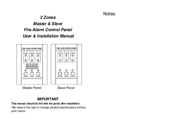
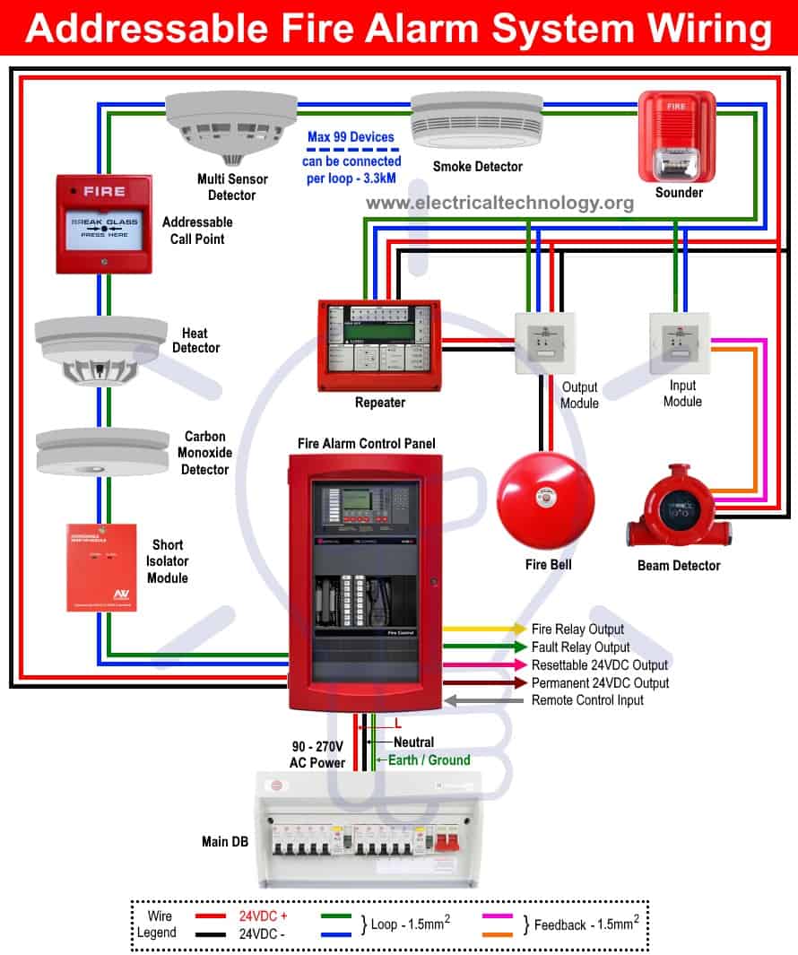
Fire alarm training system training documentation for the training of hisher staff at the purchasers detection circuit using input module class b. Fire alarm system is the combination of different components such as smoke detector heat detector carbon monoxide detector multi sensor detector call points sounders bells relay module repeater annunciator fire control panel and other related and optional security devices designed for fire alarm control system.
Types Of Fire Alarm Systems And Their Wiring Diagrams
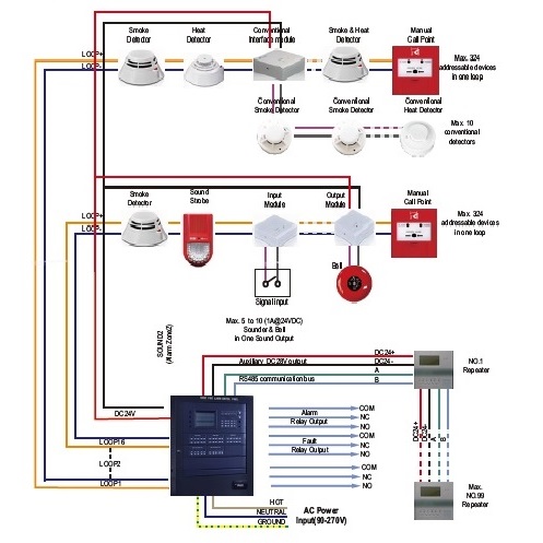
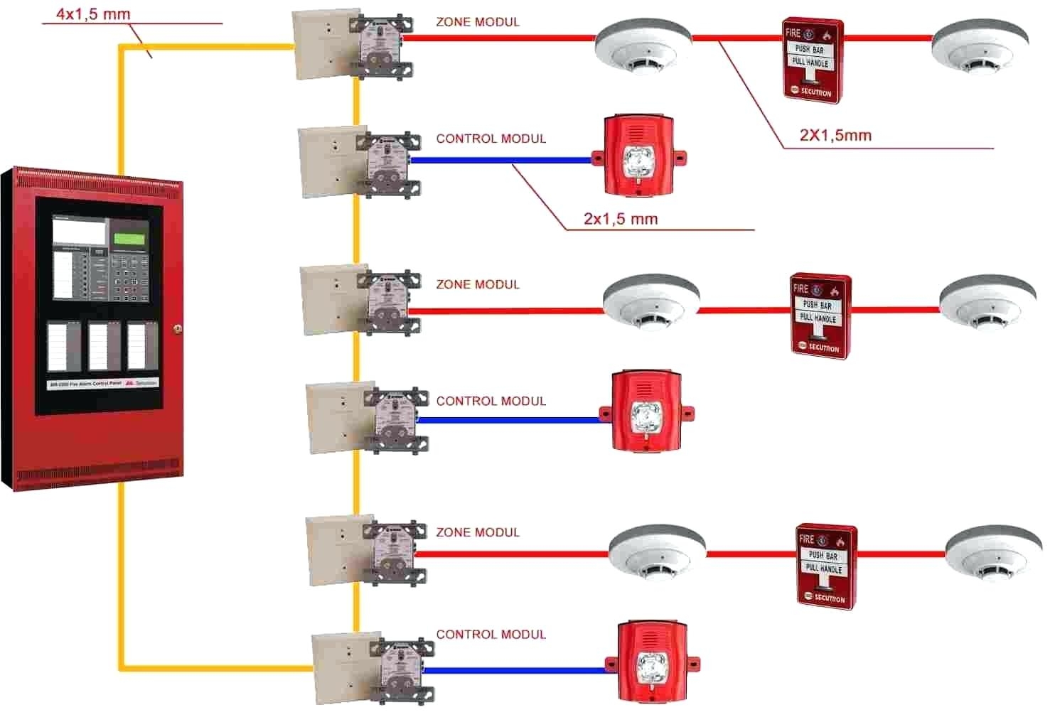
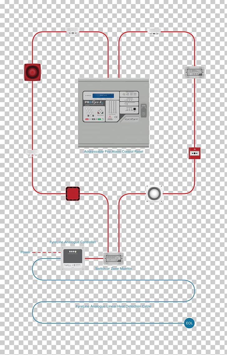
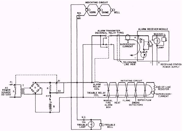
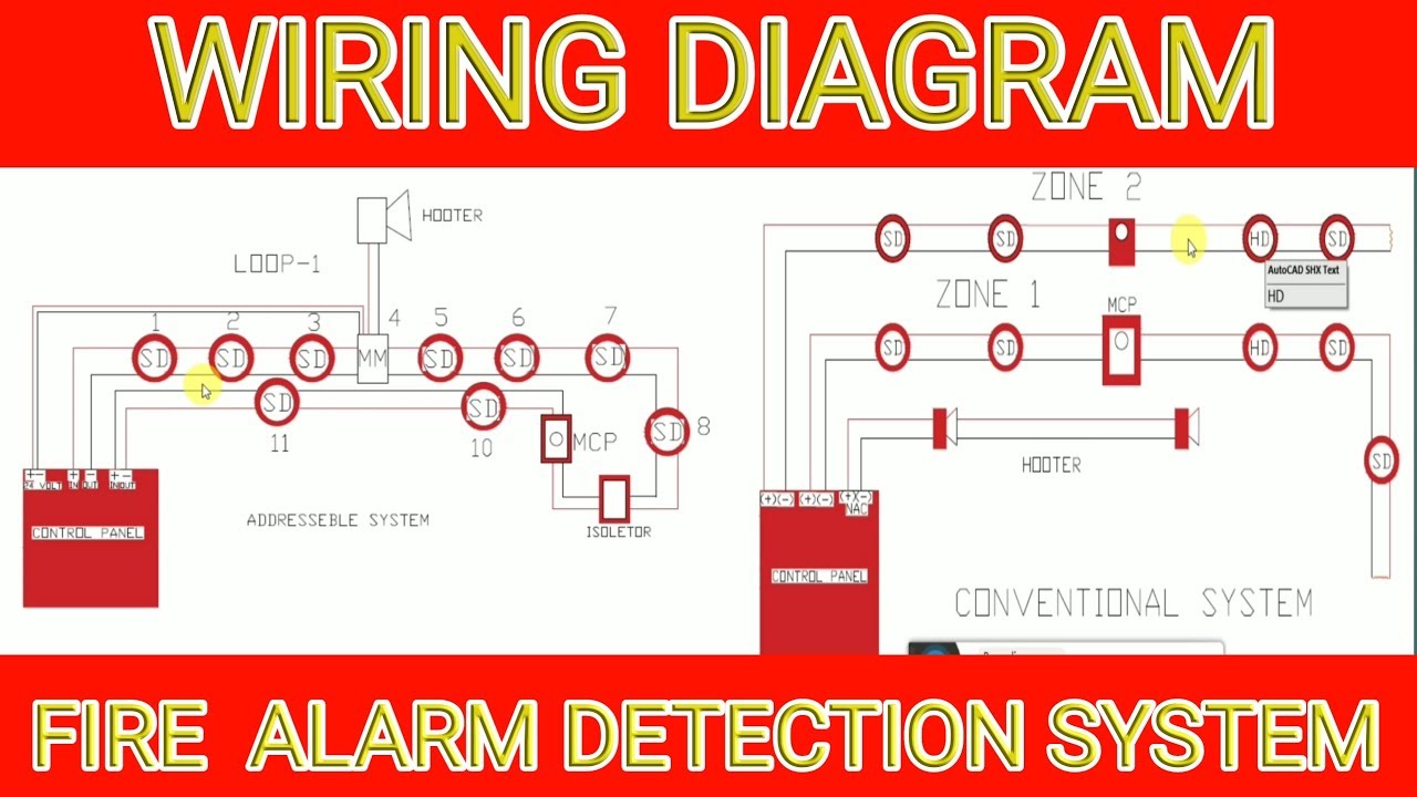
Fire alarm control panel wiring diagram. Here i show the layout diagram of fire alarm detection system. The genesis temporal horn strobe is a fire alarm notification the strobe includes a field configurable switch for selecting the figure 3. Installation wiring diagram control panel system installation manual. In the tables the letters are listed on the left on the drawings letters appear in red diamonds. Two type of fire alarm detection system 1 addressable system 2conventional system modernexpe. Room as the control panel and in rooms used by the system for the connection of alarm transmission wiring communications signaling andor power.
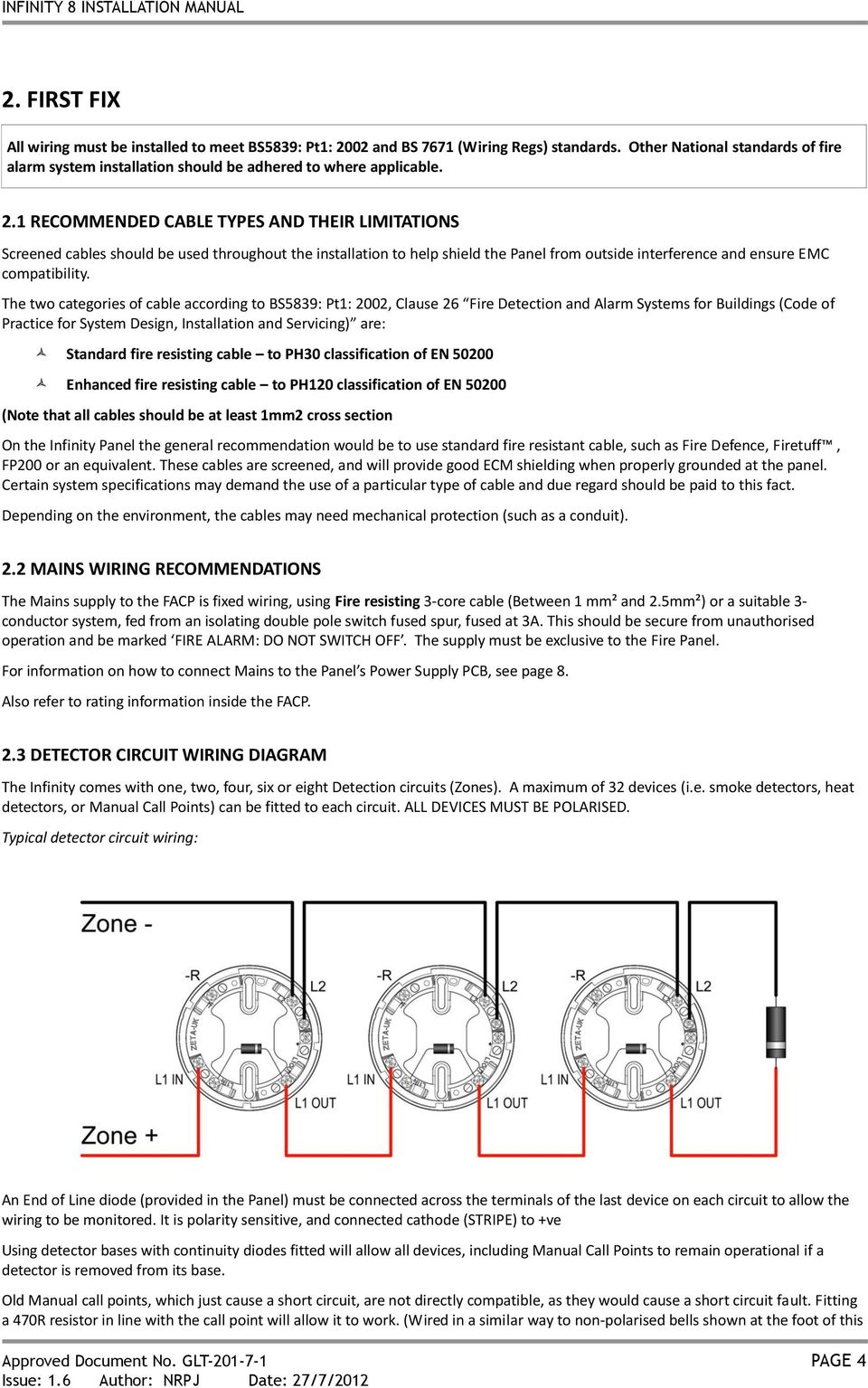
The circuit type is designated with a letter a z. 2 interlock wiring and conduit for shutdown of hvac dampers andor electric power supplies relays or shunt trip breakers. Vices can be activated by a compatible fire alarm control panel or power sup ply. Analogue addressable smoke detector with remote led. Once the circuit type. Wellborn variety of fire alarm control panel wiring diagram.
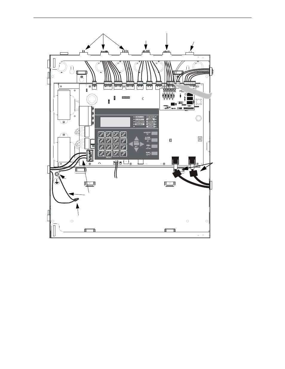
3 connection to localremote fire alarm systems listed central alarm stations or building management system. It reveals the parts of the circuit as streamlined shapes as well as the power and signal connections in between the devices. 1 120 vac or 240 vac 5060 hz power supply to the control panel. The strobes remain flashing refer to the wiring diagram fig1 yr dba refer to table 1. Audible warning devices such as bells horns strobes. Fire alarm system requirements system overview.
Connection with purchasers use of any of the products listed herein or for any section 2. A wiring diagram is a streamlined standard photographic representation of an electrical circuit. September 23 2018 by larry a. If detectors are not so located a developing fire may damage the alarm system crippling its ability to report a fire. The information shown for each control panel includes wiring diagrams and circuit tables. Smoke detectors must be installed in the same room as the control panel and in rooms used by the system for the connection of alarm transmission wiring communications signaling andor power.
Devices and a fire alarm control panel facp with remote noti in rooms used by the system for the connection of alarm transmission wiring communications and other training exercises to. By selecting a control panel. If detectors are not so located a devel oping fire may damage the alarm system compromising its abil ity to report a fire.
Gallery of Fire Alarm Control Panel Wiring Diagram