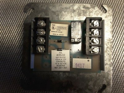
The initial timing connector is a 4 prong unit with white jumped and black lead. Control modules modules system accessories tags.

Advanced Xtralis Vep A10 P
Est m500cfs wiring diagram. Page 3 of 6 siga cr control relay typical wiring modules will accept 18 awg 075mm 2 16 10mm 14 awg 150mm and 12 awg 25mm2 wire sizes. Initial timing procedures for est. The initial timing connector is used to set initial timing of your delco est system. More of our products from edwards. Install module wiring in accordance with the job drawings and appropriate wiring diagrams figures 3 10. Make all wiring connections as shown in the wiring diagram.
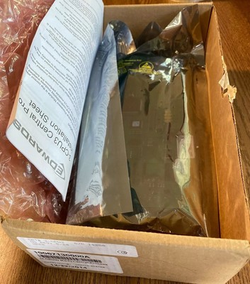
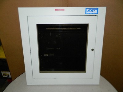
Secure the module to the electrical box supplied by installer as shown in figure 2. Peel off the removable serial number label from the module and apply. Secure this black lead to 12 volts and plug it in to the 4 prong slot on the distributor. All wiring must conform to applicable local codes ordinances and regula tions. Edwards est m500cfs 22363 20363. Available with a lead time.
Description additional information cut sheet description. Data sheet 85001 0239 issue 7 not to be used for installation purposes. Page 1 of 6 d ata s h e e t s85001 0611 not to be used for installation purposesissue 1 edwards signaling catalog u intelligent input output 09 06 13 overview edwards intelligent modules are engineered to deliver high perfor. Write the address assigned to the module on the label provided and apply the label to the module. Edwards est m500cfs quantity. Verify that all field wiring is free of opens shorts and ground faults.
This will lock the timing. Set the address on the module per job drawings. Sizes 16 awg 10mm 2 and 18 awg 075mm are preferred for ease of installationsee signature loop controller catalog sheet for.
Gallery of Est M500cfs Wiring Diagram