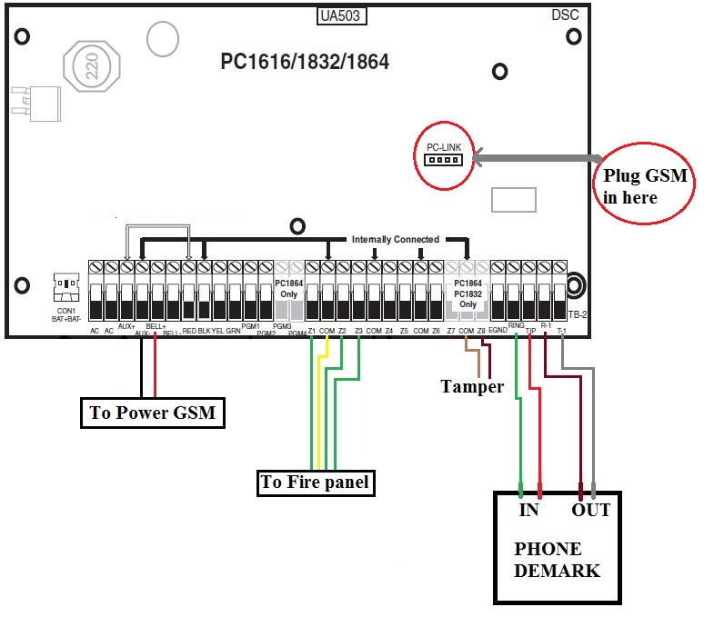
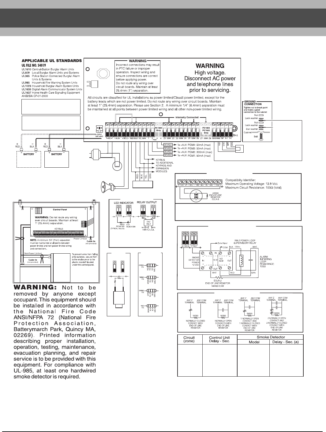
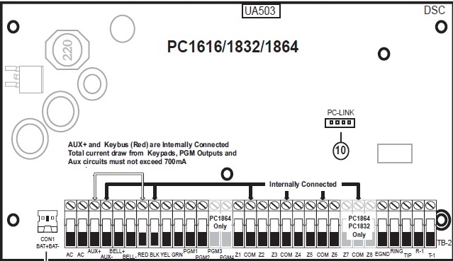
Powerseries pc1616pc1832pc1864 2 pc161618321864 wiring diagram con1 batbat 1. The 4 keybus terminals of all modules must be connected to the 4 keybus terminals of the main control panel.
Ipdkziv2 Digital Transmission System In A Zigbee 802 15 4
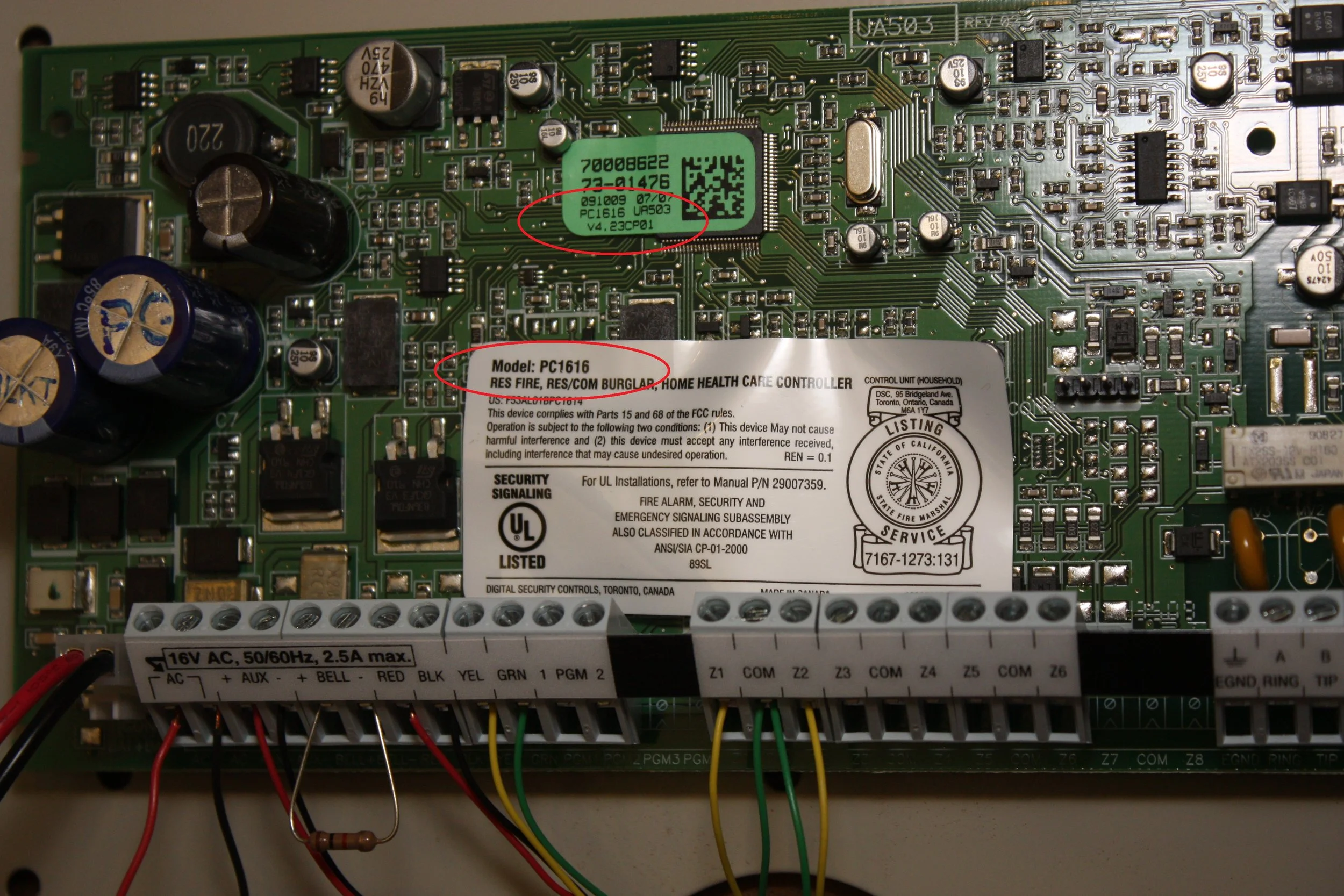
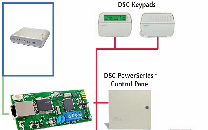
Dsc pc1832 wiring diagram. Minimum 14 64mm separation must be maintained at all points between. Position circuit board mounting holes over standoffs. Pc1616pc1832pc1864 standard wiring diagram b2 pc1616pc1832pc1864 standard wiring diagram north america only power limited stand off pc board 1. This installation guide provides the basic installation wiring and programming information required to program the powerseries pc1616 pc1832 and pc1864 control panels. Powerseries pc1616pc1832pc1864 2 11 keybus wiring the 4 wire keybus red black yellow and green is the communication connection between the control panel and all modules. The following rules must be followed when wiring the keybus.
Dialler lead wiring between permaconn and dsc pc 1832 series alarm panel. This guide shall be used in conjunction with the powerseries pc161618321864 reference. Installation wiring 1 section 1. Installation wiring this installation guide provides the basic installation wiring and programming information required to program the powerseries pc1616 pc1808 pc1832 and pc1864 control panels. Press firmly on board to snap in place. 5 optional is open close reporting must be enabled for pocket secure app.
Summary of contents for dsc pc1832 series page 1 4 must be set for tone dtmf dialling. This guide shall be used in conjunction with the powerseries pc161618321864 reference manual. Dsc pc550 dsc pc 1832 series. Insert standoff into cabinet mounting hole in the desired location. Insert stand off into cabinet mounting hole in the cable tie not supplied recommended desired location.
Gallery of Dsc Pc1832 Wiring Diagram