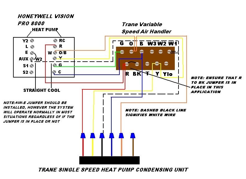
As shown in the diagram you will need to power up the thermostat and the 24v ac power is connected to the r and c terminals. It corresponds to the chart below to explain the thermostat terminal functions.

Download Indoor Heat Pump Wiring Diagram
Heat pump wiring diagram. We have other articles here that will help you with thermostat wiringthese other articles help you with thermostat wiring colors and thermostat wiring diagramsin this article we will provide specific information for wiring a heat pump for control. A wiring diagram is a streamlined traditional photographic depiction of an electrical circuit. Heat pump thermostat wiring a typical wire color and terminal diagram. A wiring diagram is a streamlined conventional photographic representation of an electrical circuit. It shows the parts of the circuit as simplified shapes and also the power as well as signal connections between the devices. A wiring diagram is a streamlined conventional photographic representation of an electrical circuit.
Goodman heat pump wiring diagram heat pump wiring diagram unique goodman air handler wiring diagram hbphelp. This way you have a reference. C is known as the common terminal. Heat pump thermostat wiring chart diagram. March 14 2020 by larry a. It shows the components of the circuit as simplified shapes and also the power and signal connections between the devices.
These two connections will ensure that there is power to the thermostat that you are operating. The color of wire r is usually red and c is black. How to wire a heat pump for control there may be a time when you will want to change your old heat pump thermostat with a new heat pump thermostat. Collection of rheem heat pump wiring diagram. The basic heat pump wiring for a heat pump thermostat is illustrated here. Before uninstalling the old thermostat take a picture of the wiring with your cell phone before removing the wires.
Variety of honeywell heat pump thermostat wiring diagram. It shows the elements of the circuit as streamlined forms and the power as well as signal connections in between the devices. Variety of 2 stage heat pump wiring diagram.
Gallery of Heat Pump Wiring Diagram