This alternator is a one of a kind hand built unit not a modified oem alternator. 240 volt 1 phase motors should use a 2 pole starter.
Diagram 3 Kicker Cvr 12 Series Wiring Diagram Free Download
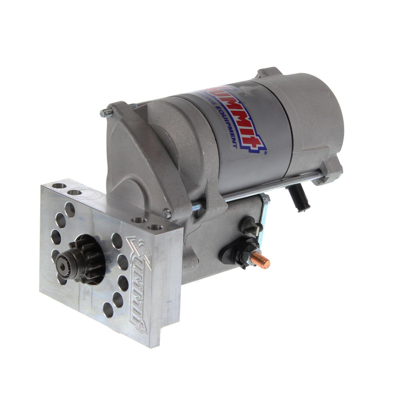
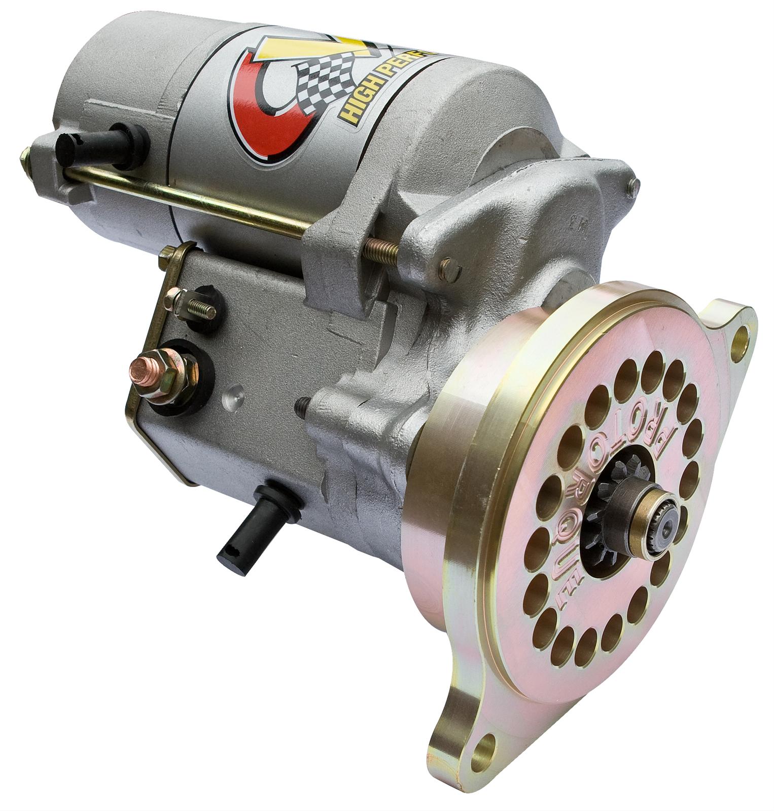
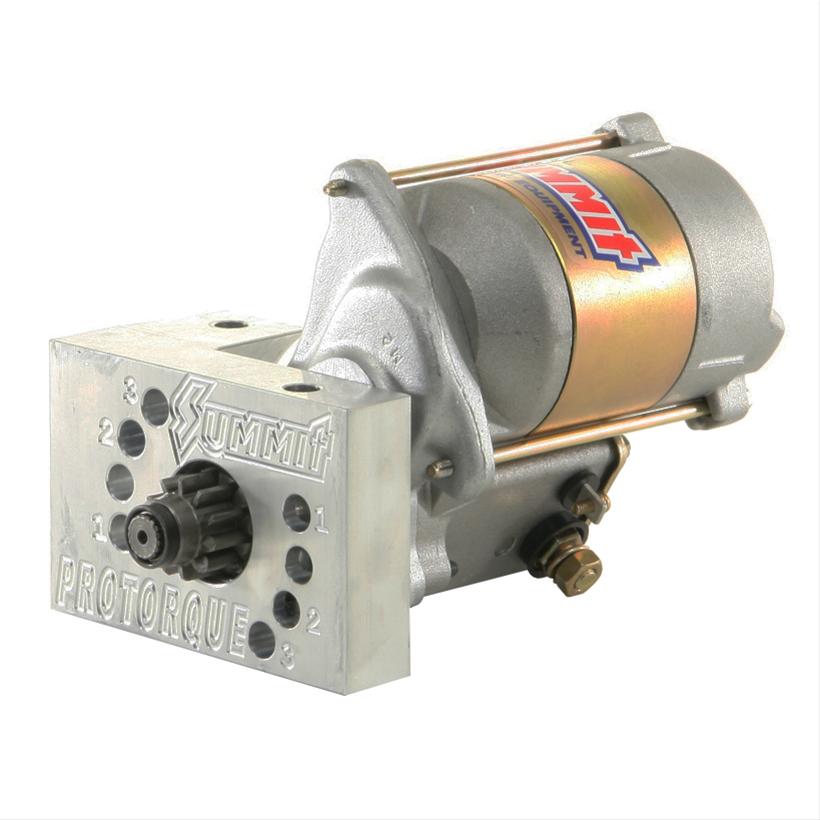
Cvr starter motor wiring diagram. Whether its a high wattage stereo system accessory lights winches for off road or towing use cbs etc. To ensure that the starter can stall automatically and the starter circuit not connected after the engine starts some cars adopt the compound relay circuit with safety driving protection. L1 is line 1 in and should be the hot black wire. The cvr protorque starter is designed to cross the flywheel between 400 and 500. This wiring should not be used on 240 volt circuits. If this occurs remove the gold tin cover held in.
This can be helpful for the two the folks and for experts whore seeking for more information regarding how to set up a functioning atmosphere. The security starter relay controlled car starter wiring diagram is as shown in the. In this case neutral white is carried through to the motor bypassing the starter altogether. The powerhouse billet is the ideal cvr alternator. In north america an induction motor will typically operate at 230v or 460v 3 phase 60 hz and has a control voltage of 115 vac or 24 vdc. Wiring starter motor to switch starter motor wiring diagram.
These alternators can handle almost anything. This is quite sufficient for this type of unit with proper shimming. Powerhouse billet one wire alternators. Wiring diagram consists of both examples and step by step directions that might enable you to actually construct your undertaking. A motor starter is a combination of devices used to start run and stop an ac induction motor based on commands from an operator or a controller. T1 is motor 1 out and goes from the starter to the motor.
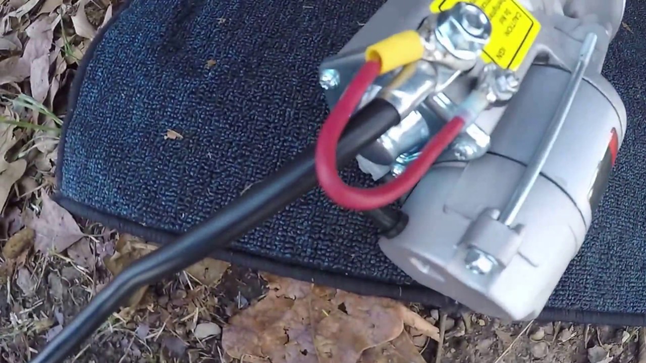
Over tightening of battery terminal may result in misalignment of solenoid contact causing intermittent starter failure. Security starter relay controlled car starter wiring diagram.
Gallery of Cvr Starter Motor Wiring Diagram