Room air cooler wiring diagram 2. Wiring diagram or pictorial.

Normal House Wiring Diagram Electrix 2011 Rmnddesign Nl
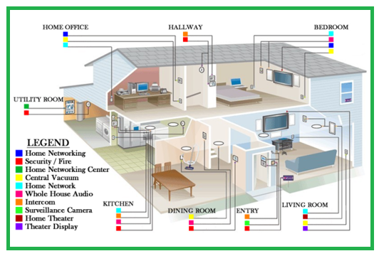
Building wiring diagram. A wiring diagram is a simple visual representation of the physical connections and physical layout of an electrical system or circuit. It shows the components of the circuit as simplified shapes and how to make the connections between the devices. With capacitor marking and installation single phase electrical wiring installation in home according to nec iec. Room air cooler electrical wiring diagram 1. A simplified conventional pictorial representation of an electrical circuit. Diagrams will show receptacles lighting interconnecting wire routes and electrical services within a home.
This is unlike a schematic diagram where the arrangement of the components interconnections on the diagram us. A wiring diagram usually gives information about the relative position and arrangement of devices and terminals on the devices to help in building or servicing the device. Three phase electrical wiring installation in home single phase electrical wiring installation in a multi story building. An electrical wiring diagram will use different symbols depending on the type but the components remain the same. It is up to the electrician to examine the total electrical requirements of the home especially where specific devices are to be located in each area and. A wiring diagram is a simplified conventional pictorial representation of an electrical circuit.
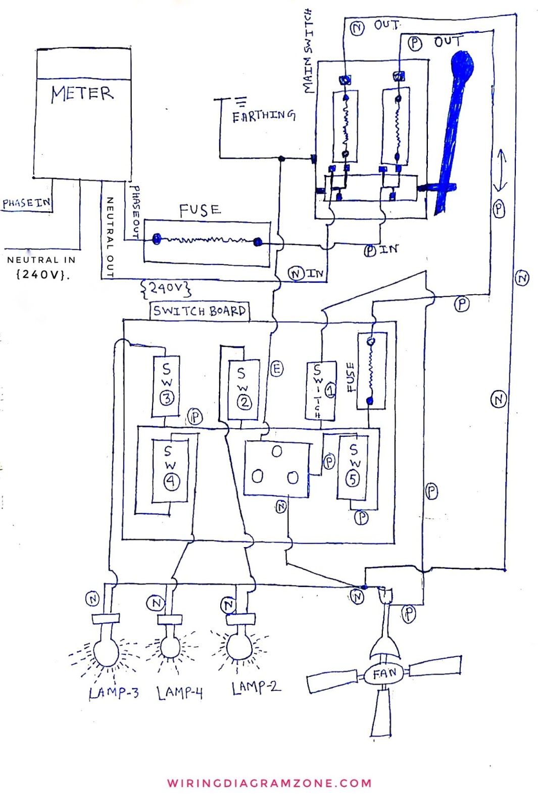
Electrical systems for an existing building then the electrical designer works to incorporate all the new electrical wiring into the existing system. When and how to use a wiring diagram. In today electrical wiring installation tutorial we will show how to wire a single phase consumer unit installation in a single storey building from utility pole to a 1 phase energy meter 1 phase distribution board and then how to connect single phase loads in single phase wiring distribution system in home electric supply system. 1 for each hot and neutral wire entering the box 1 for all the ground wires combined 1 for all the cable clamps combined if any 2 for each device switch or outlet but not light fixtures multiply the total by 2 for 14 gauge wire and 225 for 12 gauge wire to get the minimum box size required in cubic inches. Browse wiring diagram templates and examples you can make with smartdraw. The de signer must evaluate the existing electrical system to ensure that existing electrical systems can accom modate new additional electrical loads that will be imposed on them.
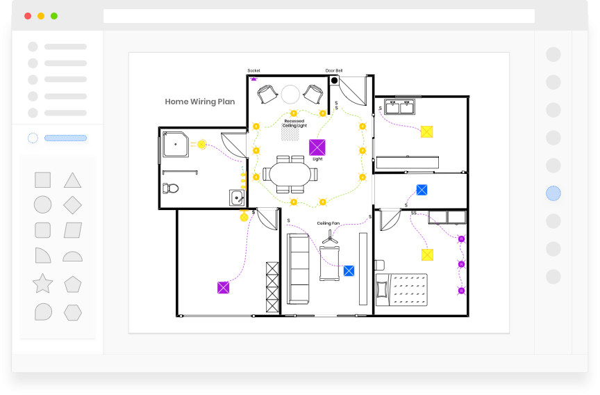
It shows how the electrical wires are interconnected and can also show where fixtures and components may be connected to the system. It shows the components of the circuit as simplified shapes and the power and signal connections between the devices. This includes circuit breaker boxes and any alarms that are wired into the system. Wiring diagrams device locations and circuit planning a typical set of house plans shows the electrical symbols that have been located on the floor plan but do not provide any wiring details.
Gallery of Building Wiring Diagram