Annunciator rod load monitoring. Page 42 figure 63 rsa iii wiring diagram gm62554g j tt 1625 717.

Annunciator Panel Psh Series
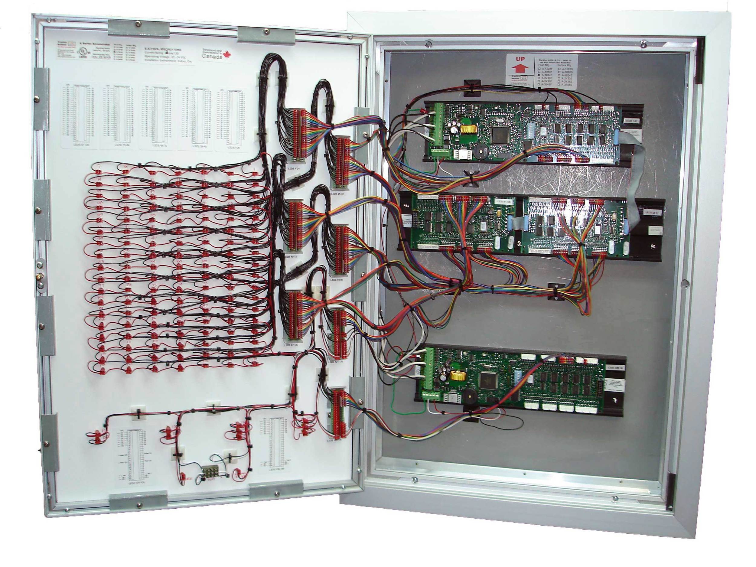
Annunciator panel wiring diagram. Rsa iii is a remote serial annunciator figure 1 figure 2 and figure 3 that monitors the condition of. Annunciator no flow status. Transfer to source 2 engine test time delay bypass audible or silent alarm and manual retransfer compliant with nfpa 110 for panel mounted control switches. Installing the 4603 9101 lcd annunciator complete the following steps to install the 4603 9101 lcd annunciator. See wiring diagram on page 7. Call points sounders bells relay module repeater annunciator fire control panel and other related and optional security devices designed for fire alarm control system.
The monitoring also includes display of source 1 and source 2. 1 connection to a power supply. Batteries wiring diagrams. Use a 2975 9206 box 2¾ in70mm deep or a 2975 9217 box 1¾ in4445 mm deep. The annunciator is equiped with modbus rtu and remote control capability including. Refer to the field wiring diagram manual 841 731 for additional details.
This terminal accepts 12 22 awg wire size. Annunciator digital out test screen. Configurations to support kohler power equipment. Annunciator purge blowdown alarm setup. Rsa iii is an annunciator panel offered in several kit. Terminate the annunciators comm and power lines as shown in figure 2.
Availability and source position. Provide dc power from the dc output of the battery back up bbu unit to the input power terminals located at the lower left corner of the ap 8000a circuit board. Like a cpu central processing unit in a computer system the fire alarm. The following wiring is required to place the annunciator into service. Annunciator digital output selection. Ups inverter wiring diagrams.
Solar panel wiring installation. Annunciator screw compressor loading.
Gallery of Annunciator Panel Wiring Diagram