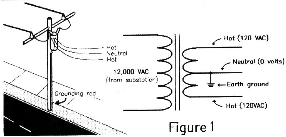
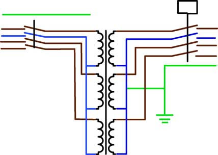
Assortment of isolation transformer wiring diagram. Electrical diagram method 1 see figure 4 for wiring connections isolation transformer system with single phase 240 volt input 120240 volt single phase output with boat grounded secondary.

Electrical Insulation Diagram Improves Medical Device Design
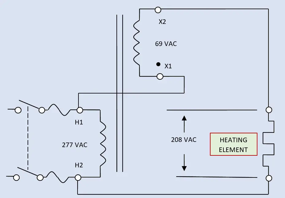
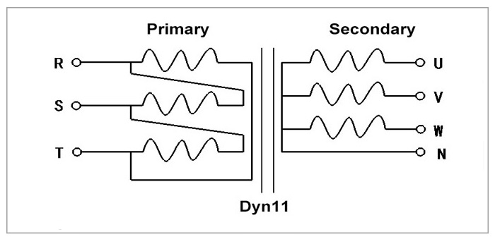
Isolation transformer wiring diagram. Select a transformer that will operate on the supply voltage available at your facility example. All the transformers in this section are rated for both 50 and 60 hz for use worldwide. A wiring diagram is a simple visual representation with the physical connections and physical layout of your electrical system or circuit. March 11 2019 by larry a. Wellborn variety of 3 phase isolation transformer wiring diagram. These diagrams do not illustrate complete systems.
In the diagram above taking an installation without an isolation transformer the device has an earth fault for example a live conductor has shorted to the chassis. To ensure compatibility check the wiring diagram by clicking a part number and viewing its product page. March 22 2019 by larry a. It shows the components of the circuit as streamlined forms as well as the power and also signal links in between the tools. Since neutral and earth are bonded in the consumer unit the system sees this as a short circuit and so a large current will flow which will blow the fuse or trip a circuit breaker. 120v 240v or 480v.
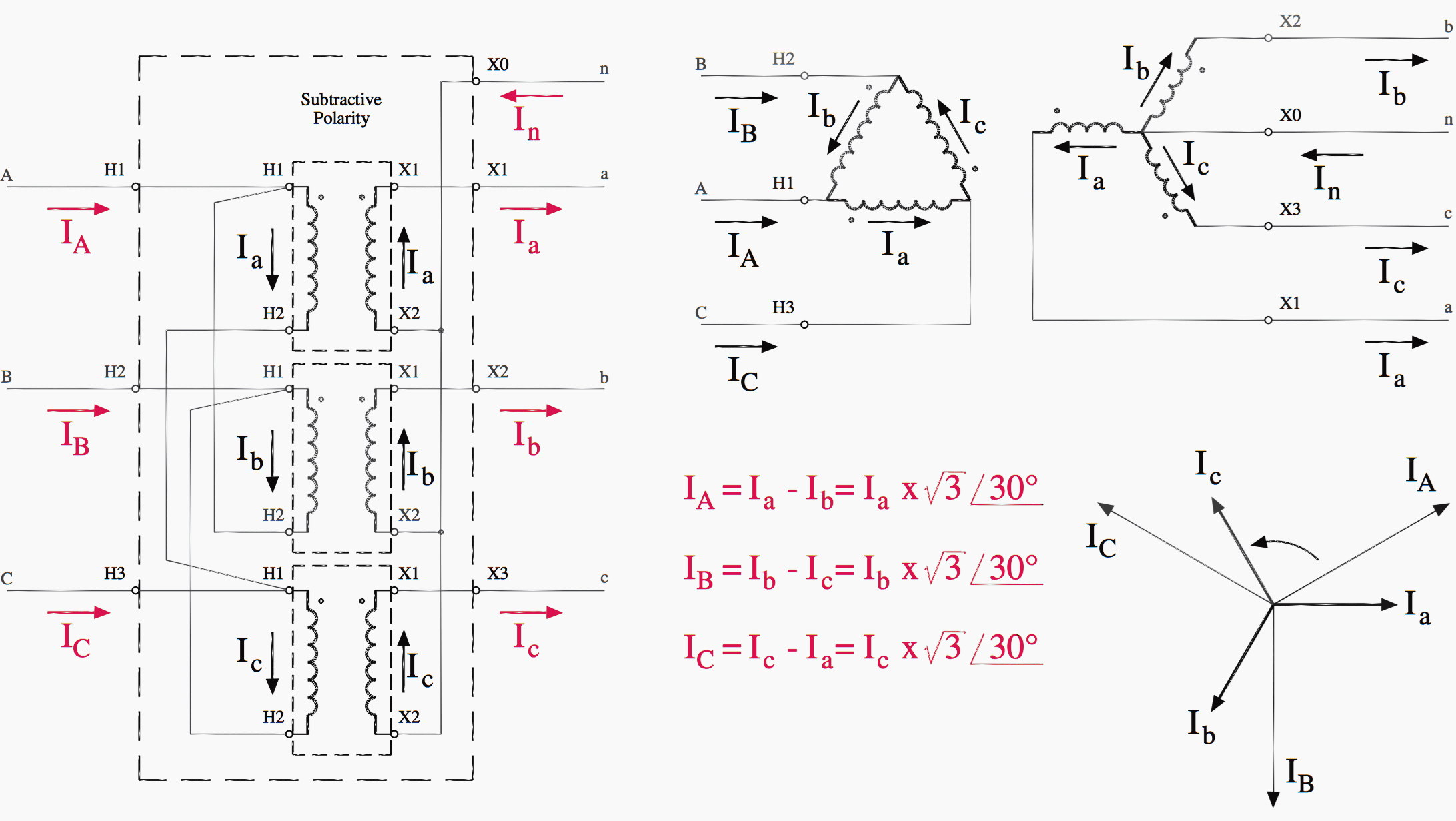
3 phase isolation transformer wiring diagram what is a wiring diagram. It shows what sort of electrical wires are interconnected and may also show where fixtures and components may be attached to the system. A wiring diagram is a streamlined traditional photographic representation of an electric circuit. A wiring diagram is a simplified standard pictorial depiction of an electrical circuit. Refer to the appropriate abyc text. It shows the elements of the circuit as simplified forms and the power as well as signal links between the gadgets.
Gallery of Isolation Transformer Wiring Diagram


.png)